
Turning tool height positioner

A technology of height locator and turning tool, which is used in metal processing mechanical parts, measuring/indicating equipment, metal processing equipment, etc., to achieve the effect of simple and accurate positioning

Inactive Publication Date: 2017-06-13
CHONGQING YONGZHONG HEAVY IND
View PDF6 Cites 0 Cited by
  • Summary
  • Abstract
  • Description
  • Claims
  • Application Information

AI Technical Summary

Problems solved by technology

[0002] Usually, during turning, the turning tool can be installed slightly lower than the turning center of the workpiece. If the turning tool is installed higher than the turning center of the workpiece, it will cause many bad phenomena

Method used


Image

  • Turning tool height positioner

Examples


Embodiment Construction

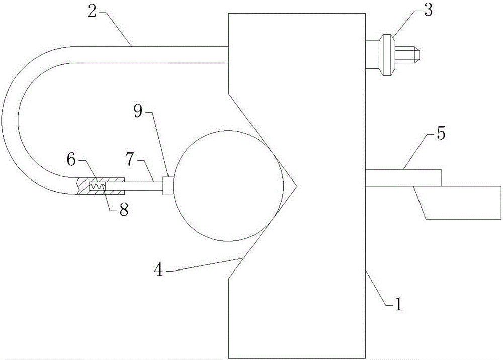
[0011] The present invention will be described in detail below in conjunction with the accompanying drawings. Such as figure 1 As shown, the turning tool height locator of the present invention includes a base block 1, an elbow pull rod 2 and a knurled nut 3, a V-shaped groove 4 is provided on one side of the base block, and a tool setting pin 5 is provided on the other side, The lower generatrix of the tool setting pin coincides with the angle bisector of the V-shaped groove, and the tail of the elbow pull rod passes through the base block and is screwed with the knurled nut so as to complete the action of loosening and clamping the workpiece. When adjusting the tool, first use a square to align the bottom surface of the base block to be perpendicular to the base surface of the tool, then clamp the workpiece to be turned between the head end of the elbow tie rod and the V-shaped groove, and make the rotation center line of the workpiece in line with the V-shaped groove. The ...


PUM


Abstract

The invention discloses a turning tool height locator, which comprises a base block, an elbow pull rod and a knurled nut. One side of the base block is provided with a V-shaped groove, and the other side is provided with a tool setting pin. The tool setting pin The lower busbar coincides with the angle bisector of the V-shaped groove, and the tail of the elbow tie rod passes through the base block and is threadedly connected with the knurled nut. The turning tool height locator with this structure can precisely position the turning tool height efficiently and conveniently.

Description

technical field [0001] The invention relates to a turning tool height positioner. Background technique [0002] Usually during turning, the turning tool can be installed slightly lower than the turning center of the workpiece. If the turning tool is installed higher than the turning center of the workpiece, it will cause many bad phenomena. Therefore, when the forming knife is cutting, the installation height of the tool will directly affect the shape and dimensional accuracy of the workpiece. Contents of the invention [0003] In view of this, the object of the present invention is to provide a turning tool height locator, which can precisely position the turning tool height efficiently and conveniently. [0004] The present invention solves the above problems through the following technical means: a turning tool height locator, including a base block, an elbow tie rod and a knurled nut, one side of the base block is provided with a V-shaped groove, and the other side is...

Claims


Application Information

Patent Timeline
Patent Type & Authority Applications(China)
IPC IPC(8): B23Q17/22
CPCB23Q17/2266
Inventor 吕本强
Owner CHONGQING YONGZHONG HEAVY IND
Learn More