Drive transmission mechanism and image forming apparatus therewith

A transmission mechanism and driving force technology, which is applied in the field of drive transmission mechanism and image forming device, can solve the problems of gear rotation fluctuation, gear surface inclination (collapse, reduction of rigidity of drive transmission mechanism, etc.), and achieve the effect of suppressing deformation

Active Publication Date: 2017-06-13
KYOCERA DOCUMENT SOLUTIONS INC
View PDF5 Cites 2 Cited by
  • Summary
  • Abstract
  • Description
  • Claims
  • Application Information

AI Technical Summary

Problems solved by technology

[0004] However, when transmitting the driving force to a driven part that requires high-precision rotation, such as a photosensitive drum, a certain degree of rigidity is required for the driving part
However, the conventional shaft correction as described above reduces the rigidity of the drive transmission mechanism.
In particular, when a relatively low-rigidity resin gear is used

Method used


Image

  • Drive transmission mechanism and image forming apparatus therewith
  • Drive transmission mechanism and image forming apparatus therewith
  • Drive transmission mechanism and image forming apparatus therewith

Examples


Embodiment Construction

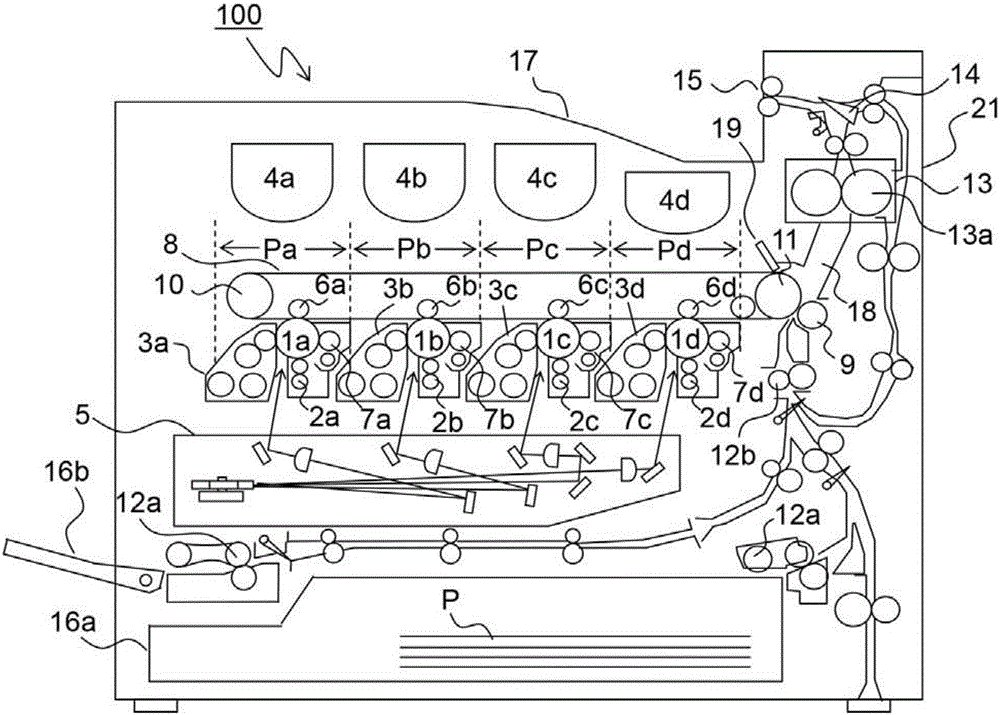
[0021] Hereinafter, an embodiment of the present invention will be described with reference to the drawings. figure 1 It is a schematic cross-sectional view showing the internal structure of the color printer 100 including the drive transmission unit 30 of the present invention. The color printer 100 is a tandem type. In the main body of the color printer 100, the four image forming sections Pa, Pb, Pc, and Pd correspond to images of four different colors (cyan, magenta, yellow, and black). upstream side ( figure 1 The left side in ) are configured in sequence.

[0022] Photosensitive drums 1a, 1b, 1c, and 1d carrying visible images (toner images) of various colors are disposed in these image forming portions Pa to Pd, and are driven around by driving means (not shown). figure 1 The intermediate transfer belt 8 rotating in the counterclockwise direction is provided adjacent to the respective image forming portions Pa to Pd. Make the photosensitive drums 1a-1d around figure...


PUM


Abstract

The invention provides a drive transmission mechanism and an iamge forming apparatus therewith. The drive transmission mechanism includes a drive transmission gear, an output-side coupling, and a first drive transmission member. The drive transmission gear includes a cylindrical boss formed at the rotation center, a circular rim concentric with the boss, and a web coupling the boss with the rim. The output-side coupling outputs a driving force of the drive transmission gear to a driven member. The first drive transmission member has higher rigidity than the drive transmission gear, and transmits the driving force of the drive transmission gear to the output-side coupling by rotating together with the drive transmission gear. The output-side coupling incline in an arbitrary direction relative to the rotation axis of the first drive transmission member, and the driving force from the drive transmission gear is transmitted to the outer circumferential rim of the first drive transmission member.

Description

technical field [0001] The present invention relates to a drive transmission mechanism mounted in an image forming apparatus such as a digital copier or a laser printer, which transmits a driving force to a member to be rotated, and an image forming apparatus including the drive transmission mechanism. Background technique [0002] Conventionally, a drive transmission mechanism used in a drive unit of an electrophotographic image forming apparatus such as a copier, a printer, a facsimile, or the like usually uses a rotating body such as a photosensitive drum or a developing roller as a driven member. As is known to the general public, in order to transmit rotational driving force to these rotating bodies, a drive transmission mechanism is composed of a drive transmission gear for transmitting the rotational driving force of a driving portion, and a coupling (coupling). Connect the rotating shaft on the rotating body (driven member) side and the rotating shaft on the driving ...

Claims


Application Information

Patent Timeline
IPC IPC(8): G03G15/00G03G21/18
CPCG03G15/757G03G21/1857G03G21/1647F16D1/02F16D1/10F16D2001/102F16H55/17G03G15/1615
Inventor 上野大二郎向井健一
Owner KYOCERA DOCUMENT SOLUTIONS INC
Why Eureka
Try Eureka