Stator core, stator and motor

A stator core and stator technology, which is applied to electrical components, electromechanical devices, electric components, etc., can solve the problems of increasing iron core and winding material consumption, increasing cost, lengthening the axial size of the yoke and teeth, etc. The effect of magnetic concentration and cost reduction

Active Publication Date: 2017-06-13
GUANGDONG WELLING ELECTRIC MACHINE MFG +1
View PDF7 Cites 0 Cited by
  • Summary
  • Abstract
  • Description
  • Claims
  • Application Information

AI Technical Summary

Problems solved by technology

[0002] In the motor in the related art, the stator yoke, teeth and tooth shoe are punched out as one piece, so the dimensions of the yoke, tooth and tooth shoe in the axial direction of the stator are consistent. For a unit surface area For a rotor with a weak magnetic field or a low rotation frequency, in order to save stator materials and improve its performance, the size of the yoke and teeth needs to be thinner and the area of ​​the tooth shoe larger, but affected by the radius of the inner circle of the stator, through Increasing the width of the tooth shoe to increase the area of ​​the tooth shoe has limited effect, and if the tooth shoe is expanded in the axial direction of the stator, the axial dimension of the yoke and the teeth will be lengthened, thereby increasing the material consumption of the iron core and winding, resulting in an increase in cost

Method used


Image

  • Stator core, stator and motor
  • Stator core, stator and motor
  • Stator core, stator and motor

Examples


Embodiment Construction

[0045] Embodiments of the invention are described in detail below, examples of which are illustrated in the accompanying drawings. The embodiments described below with reference to the accompanying drawings are exemplary, intended to explain the present invention, but not to be construed as limitations of the present invention, those skilled in the art can change the above-mentioned embodiments within the scope of the present invention , modification, substitution and variation.

[0046] The motor and its stator according to the embodiments of the present invention will be described in detail below with reference to the accompanying drawings.

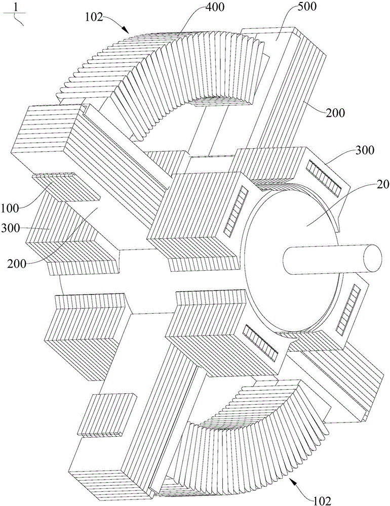
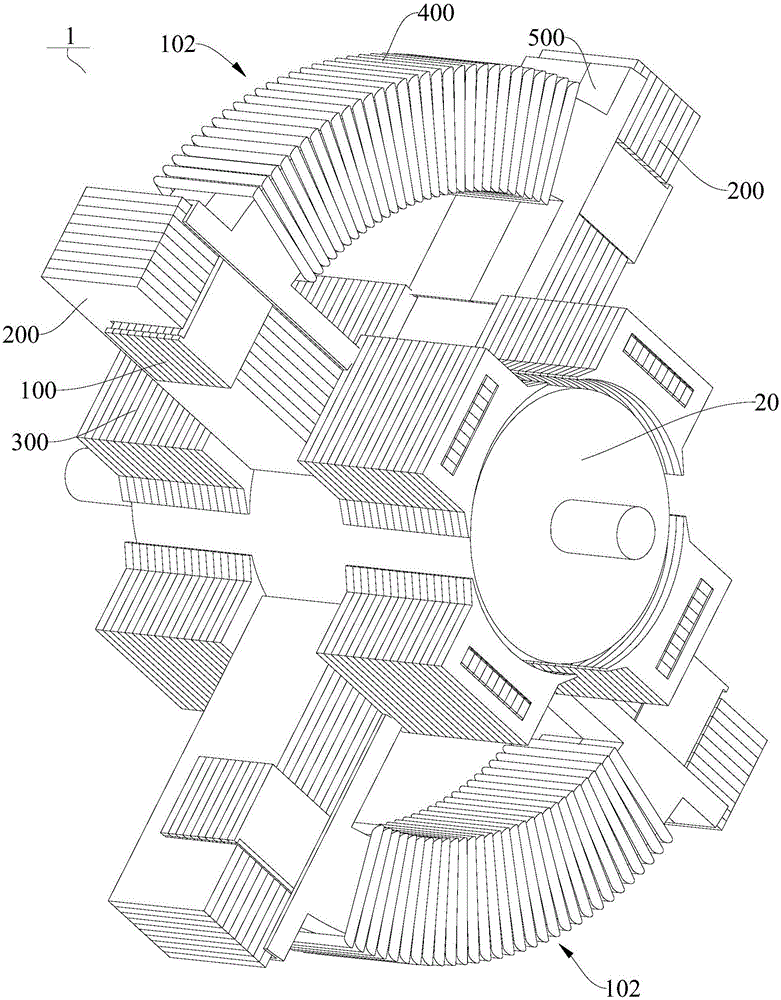
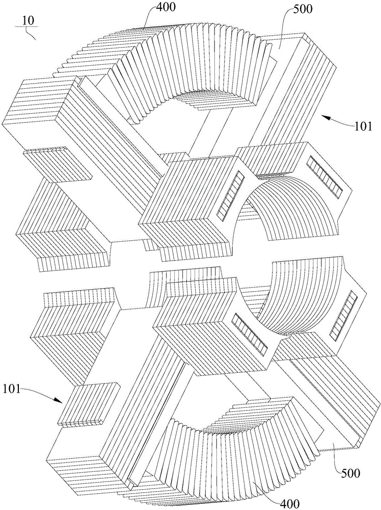
[0047] refer to Figure 1 to Figure 12 As shown, the motor 1 according to the embodiment of the present invention may include a rotor 10 and a stator 20, the stator 10 is arranged on the outer periphery of the rotor 20, and the rotor 20 is rotatably fitted in the stator 10, wherein the rotor 20 may be a permanent magnet magnetic ring r...


PUM


Abstract

The invention discloses a stator core, a stator and a motor. The stator core is arranged at the periphery of a rotor and comprises a plurality of single stators, the single stators are arranged at intervals along a circumferential direction, each single stator comprises a yoke part, two main tooth parts and a tooth boot part, the yoke part is formed by laminating a plurality of yoke part punching sheets along an axial direction of the rotor, the plurality of yoke part punching sheets extend along the circumferential direction of the rotor, the two main tooth parts are respectively clamped at two ends of the circumferential direction of the yoke part, each main tooth part is formed by laminating a plurality of tooth part punching sheets, the plurality of tooth part punching sheets are perpendicular to the yoke part and extend along a radial direction of the yoke part, an extension part is arranged at an inner end of the main tooth part and extends along an axial direction of the yoke part, at least one end of the extension part protrudes out of the main tooth part, the tooth boot part is formed by laminating a plurality of tooth boot punching sheets, a closed groove is formed in the tooth boot part and penetrates through the tooth boot part along the axial direction of the yoke part, and the extension part is clamped in the closed groove. By the stator core according to the embodiment of the invention, the magnetism gathering capability can be improved, and the cost is reduced.

Description

technical field [0001] The invention relates to the technical field of motors, in particular to a stator core, a stator with the stator core and a motor with the stator. Background technique [0002] In the motor in the related art, the stator yoke, teeth and tooth shoe are punched out as one piece, so the dimensions of the yoke, tooth and tooth shoe in the axial direction of the stator are consistent. For a unit surface area For a rotor with a weak magnetic field or a low rotation frequency, in order to save stator materials and improve its performance, the size of the yoke and teeth needs to be thinner and the area of ​​the tooth shoe larger, but affected by the radius of the inner circle of the stator, through Increasing the width of the tooth shoe to increase the area of ​​the tooth shoe has limited effect, and if the tooth shoe is expanded in the axial direction of the stator, the axial dimension of the yoke and the teeth will be lengthened, thereby increasing the mater...

Claims


Application Information

Patent Timeline
IPC IPC(8): H02K1/14H02K1/18
CPCH02K1/14H02K1/185
Inventor 李春江陈金涛
Owner GUANGDONG WELLING ELECTRIC MACHINE MFG
Why Eureka
Try Eureka