
Novel workpiece bending device

A technology of bending device and workpiece, applied in the field of workpiece bending, can solve the problems of low processing efficiency, high operation risk, time-consuming and labor-consuming, etc., and achieve the effects of low manufacturing cost, high precision and simple structure

Active Publication Date: 2017-06-20
NANTONG GOD OF HORSES THREAD
View PDF5 Cites 0 Cited by
  • Summary
  • Abstract
  • Description
  • Claims
  • Application Information

AI Technical Summary

Problems solved by technology

[0002] At present, bending devices are often used in the bending process of workpieces. Some traditional bending devices require manpower to apply force by themselves. The operation process is not only time-consuming and labor-intensive, but also inefficient. , but due to the material of the workpiece itself or the stamping force is too large, the stamped and bent workpiece is bonded to the mold, and it is not easy to fall off and needs to be separated manually. The operation is extremely dangerous and the processing efficiency is low, and there is a big safety hazard

Method used

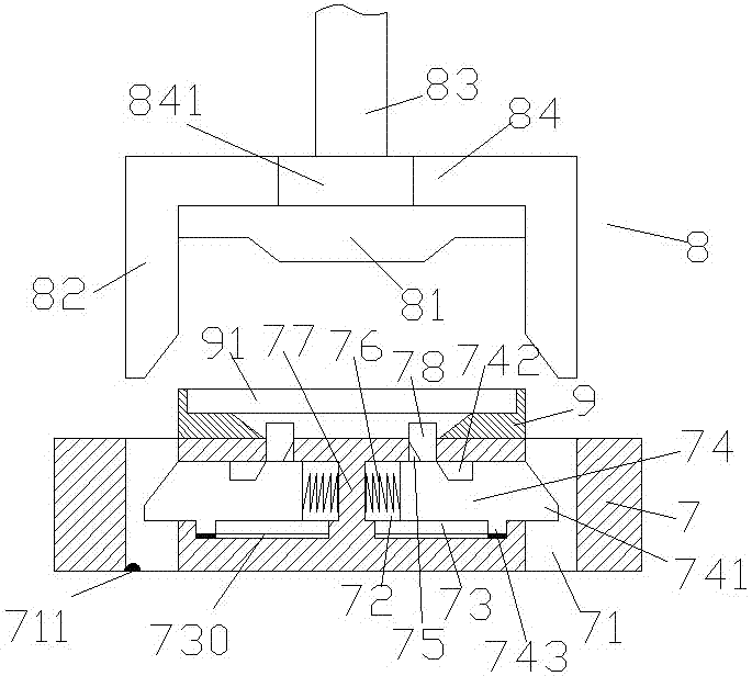
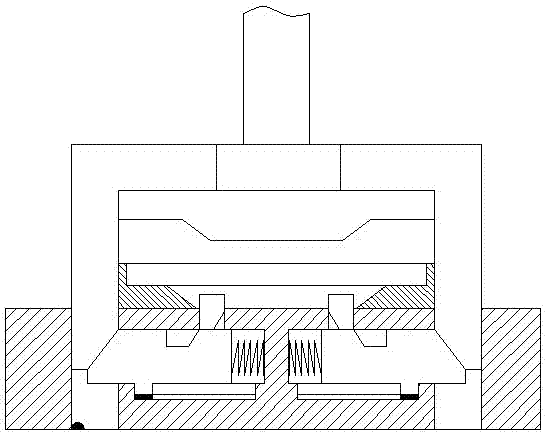
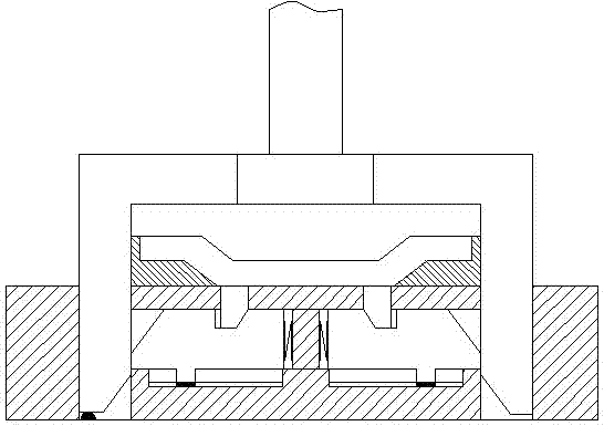

Image

  • Novel workpiece bending device
  • Novel workpiece bending device
  • Novel workpiece bending device

Examples


Embodiment Construction

[0020] Such as Figure 1-Figure 4 As shown, a novel workpiece bending device of the present invention includes a manipulating part 8 and a base part 7 arranged at the lower end of the manipulating part 8. The manipulating part 8 includes a pressing arm 84, an upper template 81 and a driving Arm bar 83, both ends of the pressing arm bar 84 are fixed with inserting shafts 82 extending downwards, the upper part of the base part 7 is provided with a lower template 9 corresponding to the upper template 81, the inserting The base part 7 corresponding to the lower end of the shaft 82 is provided with a slot 71 for cooperating with the insertion shaft 82, and the base part 7 between the slots 71 is provided with slides corresponding to the left and right. Sliding grooves 72, spacers 77 fixedly connected to the base part 7 are arranged between the sliding grooves 72, and the upper part of each of the sliding grooves 72 is provided with the body passing through the base part 7 and The ...


PUM


Abstract

The invention discloses a novel workpiece bending device which comprises an operation part and a base part arranged at the lower end of the operation part. The operation part internally comprises a pressure applying arm rod, an upper mold plate and a driving arm rod, the two ends of the pressure applying arm rod are each fixedly provided with an insertion shaft extending downwards, a lower mold plate corresponding to the upper mold plate is arranged at the upper portion of the base part, a slot is formed in the position, corresponding to the lower end of each insertion shaft, in the base part, sliding grooves arranged in a left-and-right corresponding manner are formed in the position, between the slots, of the base part, and a separating block fixedly connected with the base part is arranged between the sliding grooves; the upper portion of each sliding groove is provided with a through groove penetrating a body of the base body and communicated with the inner bottom face of the lower mold plate, and an ejection block is arranged in each through groove; and a sliding cavity is formed in the bottom face of each sliding groove, a sliding rail is arranged on the inner bottom face of each sliding cavity, a sliding rod is arranged in each sliding groove in a sliding manner, a tension spring is arranged between each sliding rod and the separating block, and a sliding hole is formed in the upper portion of each sliding rod. The novel workpiece bending device is simple in structure, automatic ejection can be achieved after punching is completed, the manufacturing cost is low, and maintenance is convenient.

Description

technical field [0001] The invention relates to the technical field of workpiece bending, in particular to a novel workpiece bending device. Background technique [0002] At present, bending devices are often used in the bending process of workpieces. Some traditional bending devices require manpower to apply force by themselves. The operation process is not only time-consuming and labor-intensive, but also inefficient. However, due to the material of the workpiece itself or the excessive stamping force, the stamped and bent workpiece is bonded to the mold, and it is not easy to fall off and needs to be separated manually. The operation is extremely dangerous and the processing efficiency is low, and there is a large safety hazard. Contents of the invention [0003] The technical problem to be solved by the present invention is to provide a novel workpiece bending device, which can solve the above-mentioned problems in the prior art. [0004] The present invention is achi...

Claims


Application Information

Patent Timeline
IPC IPC(8): B21D11/00B21D45/04B21C51/00
CPCB21C51/00B21D11/00B21D45/04
Inventor 范含晶
Owner NANTONG GOD OF HORSES THREAD
Learn More