
Locking mechanism of automobile seat slide rail

A technology of car seat slide rail and locking mechanism, which is applied to vehicle seats, movable seats, special positions of vehicles, etc., can solve the problem that deformation cannot be guaranteed, the impact of vehicle strength cannot be satisfied, and locking stability cannot be guaranteed. And reliability and other issues, to achieve the effect of no self-locking, small footprint, simple structure

Pending Publication Date: 2017-06-20
JIANGSU ZHONGMING XIANGHE SEIKO
View PDF7 Cites 4 Cited by
  • Summary
  • Abstract
  • Description
  • Claims
  • Application Information

AI Technical Summary

Problems solved by technology

However, this method of using plastic deformation of the material to achieve locking and anti-escapement cannot guarantee the stability and reliability of the locking because it cannot guarantee that the material will deform in an ideal state when the slide rail is subjected to high-strength impact.
At the same time, with the development of automobile technology, the driving speed of automobiles is getting higher and higher, and the safety requirements for car seat slide rails are also getting higher and higher. However, existing car seat slide rails, especially car seat slide rails The locking mechanism of the rail has been unable to meet the stringent requirements of the vehicle to withstand higher impacts

Method used


Image

  • Locking mechanism of automobile seat slide rail
  • Locking mechanism of automobile seat slide rail
  • Locking mechanism of automobile seat slide rail

Examples


Embodiment Construction

[0021] The applicant will describe in detail in the form of the following examples, but the description of the examples is not a limitation to the technical solution of the present invention, and any equivalent transformation made according to the concept of the present invention is only a formal rather than a substantive equivalent transformation All should be regarded as the scope of the technical solution of the present invention.

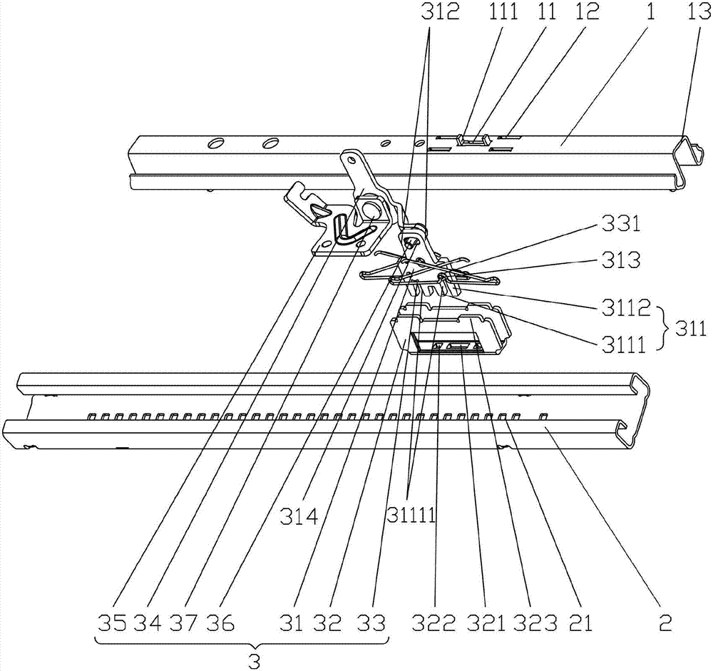
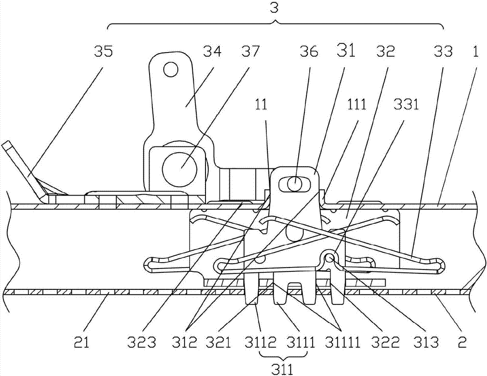
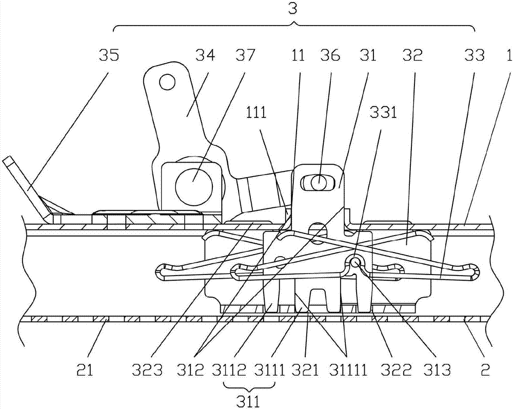
[0022] In the following descriptions, all concepts related to directionality or orientation of up, down, left, right, front and back are based on figure 1 The position shown is a reference, so it cannot be understood as a special limitation on the technical solution provided by the present invention.

[0023] Please refer to figure 1 and combine figure 2 , image 3, the present invention is a kind of locking mechanism of car seat slide rail, described car seat slide rail comprises moving guide rail 1, fixed guide rail 2 and is located at the...


PUM


Abstract

The invention provides a locking mechanism of an automobile seat slide rail. The automobile seat slide rail comprises a mobile guide rail, a fixing guide rail and a locking mechanism. The locking mechanism comprises a locking paw, a fixing rack, locking springs, an operation wrench and a fixing rack. The lower end of the lock paw is provided with locking teeth. The locking teeth are composed of long and short locking teeth. Locking teeth guide surfaces are arranged at side surfaces of a pair of short locking teeth. A locking paw guide surface is arranged at the upper end of the locking paw. A guide hole is formed in the bottom center of the fixing rack, and square holes are formed in two sides of the fixing rack. The guide hole of the locking teeth coordinates with the guide surface of the locking teeth through a gap. A pair of locking springs are arranged at front and rear sides of the locking paw. The operation wrench is connected with one end of the locking paw. The fixing rack is connected with the operation wrench. The mobile guide rail forms a locking paw guide hole in the installation surface. Exhaust holes are formed in the bottom of the fixing guide rail in intervals. The distance between adjacent two locking exhaust holes is matched with the distance between two locking teeth. The locking strength is high, the simultaneity is good without self-locking, the gap is small, the anti-impact capability is strong to keep the locking stable, the reliability is good, and the space occupation is small.

Description

technical field [0001] The invention belongs to the technical field of vehicle accessories, and in particular relates to a locking mechanism for a slide rail of an automobile seat. Background technique [0002] The car seat slide usually includes a moving guide, a fixed guide and a locking mechanism. Its function is to change the front and rear positions of the seat and lock the seat. Therefore, the locking mechanism of the car seat slide is required. At present, the locking mechanisms commonly used on the slide rails of motor vehicle seats on the market mainly include three types: single-side locking, double-side locking and bottom locking. Each has its own achievements, but in practical applications, compared with the other two structures, the bottom locking structure has higher impact resistance after locking. This can be obtained in detail through the previously disclosed Chinese invention patent authorization announcement number CN103085684B. The patented technical s...

Claims


Application Information

Patent Timeline
IPC IPC(8): B60N2/08B60N2/07
CPCB60N2/0722B60N2/08
Inventor 邹耀忠
Owner JIANGSU ZHONGMING XIANGHE SEIKO
Learn More