Separative supply device of compression coil spring

A technology for compressing coil springs and supplying devices, applied in the directions of transportation, packaging, conveyors, etc., can solve the problems of inability to be directly practical in industrial sites, low efficiency of kinked springs, and lack of general activation, so as to improve separation efficiency and discharge efficiency, The effect of reducing manufacturing cost and improving reliability

Inactive Publication Date: 2017-06-20
黄镇镐
View PDF6 Cites 2 Cited by
  • Summary
  • Abstract
  • Description
  • Claims
  • Application Information

AI Technical Summary

Problems solved by technology

[0002] Usually, a compression coil spring is formed into a bar-shaped rod, and a predetermined clearance is generated between the coils to form a large number of compression coil springs in a former, and the compression coil springs are kinked during storage and transportation. , so there is a problem that it cannot be directly used at the industrial site after storage and transportation
[0003] In the past, when storing and transporting a plurality of compression coil springs formed as described above, the development of a technology that can be easily separated and supplied even if they are kinked has been continuously carried out. As a conventional spring supply device, a utility model was disclosed in Korea in 1994. It is disclosed in No. 15771 (published on July 22, 1994) that as a unit for removing the kinks of the springs, reflectors and high-pressure air soft tubes are arranged in a manner facing each other on the guides of more than 15 rows and the side ends of the guides. tube, to inject high-pressure air, so that the spring collides with the reflector to separate, but as mentioned above, only by injecting air in one direction to make the air collide with the opposite reflector, it is impossible to make the kinked spring The efficiency of the separation is extremely low, so the device is not widely activated
[0004] As another example of a spring feeder, as described in Korean Laid-Open Patent No. 1996 No. 34036 (published on October 22, 1996) or Authorized Patent No. 1411983 (announced on June 26, 2014), a spring feeder developed to supply air and The technique of supplying vibration with electromagnets and leaf springs or supplying air together with a vibrating feeder, but in order to use this vibration to align or separate springs, an additional vibration generating unit that generates vibration is required, which increases the cost of the device At the same time, there are many problems such as serious noise due to vibration

Method used


Image

  • Separative supply device of compression coil spring
  • Separative supply device of compression coil spring
  • Separative supply device of compression coil spring

Examples


Embodiment Construction

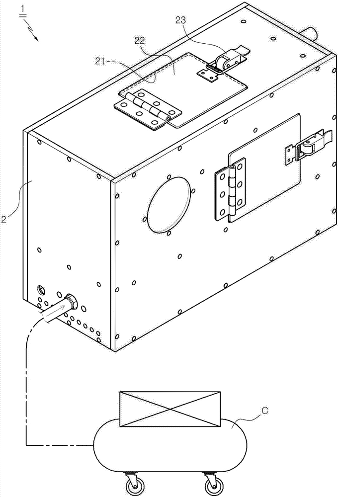
[0024] The present invention relates to a separate supply device for compressed coil springs. After forming a large number of rod-shaped rods into helical compressed coil springs in a former, they are twisted with each other during storage and transportation. It can be supplied individually by using a twisted compression coil spring, and it can be supplied separately. Figure 1 A more specific description of this is as follows.

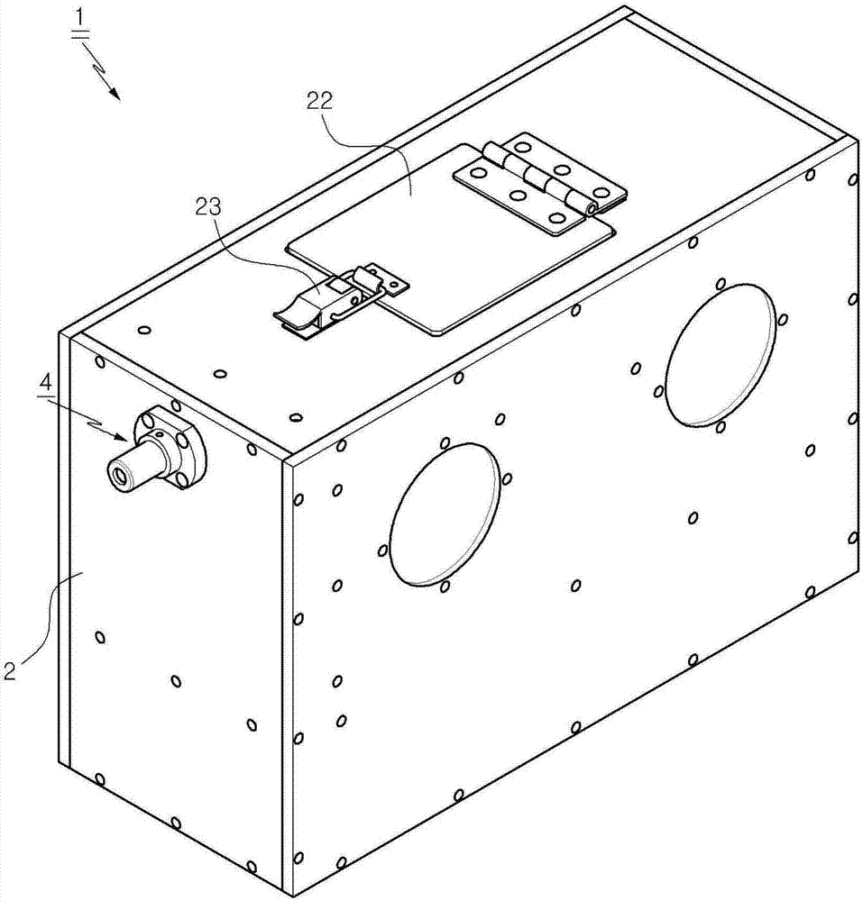
[0025] As shown rear and right side profile figure 1 and showing the front and left sides figure 2 The above-mentioned separation supply device 1 of the above-mentioned compression coil spring S of the present invention is in the main body part 2 that is formed by hexahedron, after above-mentioned molding as above, with the mode that can throw in the compression coil spring S of kinking, insert opening 21 through inwardly and outwardly to form, input The mouth 21 is opened and closed by the input door 22 provided with the locking unit 23 such as th...


PUM


Abstract

The invention provides a separative supply device of a compression coil spring, wherein individual supplying is realized through separating entangled compression coil springs. The device includes: a discharge gate which performs individual discharge after a front surface part of a body part is separated from a separation space; an inclination guide unit which is formed through inclination at the lower side of an inlet in a downward direction; a horizontal conveying part including multiple horizontal sliding plates on the lower part of the separation space and horizontal air spray holes which spray high-pressure air to the front from the lower part of a tip; a vertical conveying unit including curved sliding plates linked to the front part of the horizontal conveying unit and vertical air spray holes which spray high-pressure air in an upward direction from the tip of the curved sliding plates; and a guide block which guides the compression coil springs to the upper part of the vertical conveying unit.

Description

technical field [0001] The present invention relates to a separating and supplying device for compression coil springs, and more specifically relates to a separating and supplying device for compression coil springs, which separates the compressed coil springs that are kinked to each other during storage and transfer after forming the compression coil springs so that they can be separated individually. Background technique [0002] Usually, a compression coil spring is formed into a bar-shaped rod, and a predetermined clearance is generated between the coils to form a large number of compression coil springs in a former, and the compression coil springs are kinked during storage and transportation. , Therefore, there is a problem that it cannot be directly used at the industrial site after storage and transportation. [0003] In the past, when storing and transporting a plurality of compression coil springs formed as described above, the development of a technology that can ...

Claims


Application Information

Patent Timeline
Patent Type & Authority Applications(China)
IPC IPC(8): B65G51/03
CPCB65G51/035
Inventor 黄镇镐
Owner 黄镇镐
Why Eureka
Try Eureka