Port replicator

a replicator and port technology, applied in the field of port replicators, can solve the problems of limited or short range of movement within which the separation button b>14/b> can be pressed and moved, the operation of the catching hook , the inability to move smoothly. to achieve the effect of smooth separation

Inactive Publication Date: 2005-12-29
LG ELECTRONICS INC
View PDF3 Cites 31 Cited by
  • Summary
  • Abstract
  • Description
  • Claims
  • Application Information

AI Technical Summary

Benefits of technology

[0013] Accordingly, the present invention is conceived to solve one or more of the aforementioned drawbacks in the related art. An object of the present invention is to provide a port replicator from which a portable computer can be smoothly separated.
[0025] According to the present invention configured as above, the portable computer can be more easily separated from the port replicator as compared to the related art. In particular, since the portable computer can be handled with one hand while the actuating lever of the port replicator can also be handled with the other hand, there is an advantage in that the convenience of the port replicator is enhanced.
[0026] In addition, since the fastening and unfastening operations of the catching hooks are produced while the cam followers are guided along the cam slots, the cam followers do not run off tracks along the cam slots even due to any external forces. Therefore, there is another advantage in that the operating reliability of the port replicator is enhanced.

Problems solved by technology

However, the aforementioned related art has several drawbacks.
However, a range of movement within which the separation button 14 can be pressed and moved is limited or short.
Therefore, there are problems in that the operation of the catching hooks 13 and 13′ are not relatively smooth and a large force is required in separating a portable computer from the port replicator 10.
Therefore, there is another problem in that the catching hooks 13 and 13′ do not work well when the spring is weakened or its assembled state is poor.

Method used


Image

  • Port replicator
  • Port replicator
  • Port replicator

Examples


Embodiment Construction

[0039] This application is related to a co-pending, commonly assigned application entitled “AN ANTITHEFT DEVICE FOR A PORT REPLICATOR,” filed on even date herewith, the contents of which are herein incorporated by reference.

[0040] Hereinafter, a port replicator according to the present invention will be described in detail with reference to the accompanying drawings.

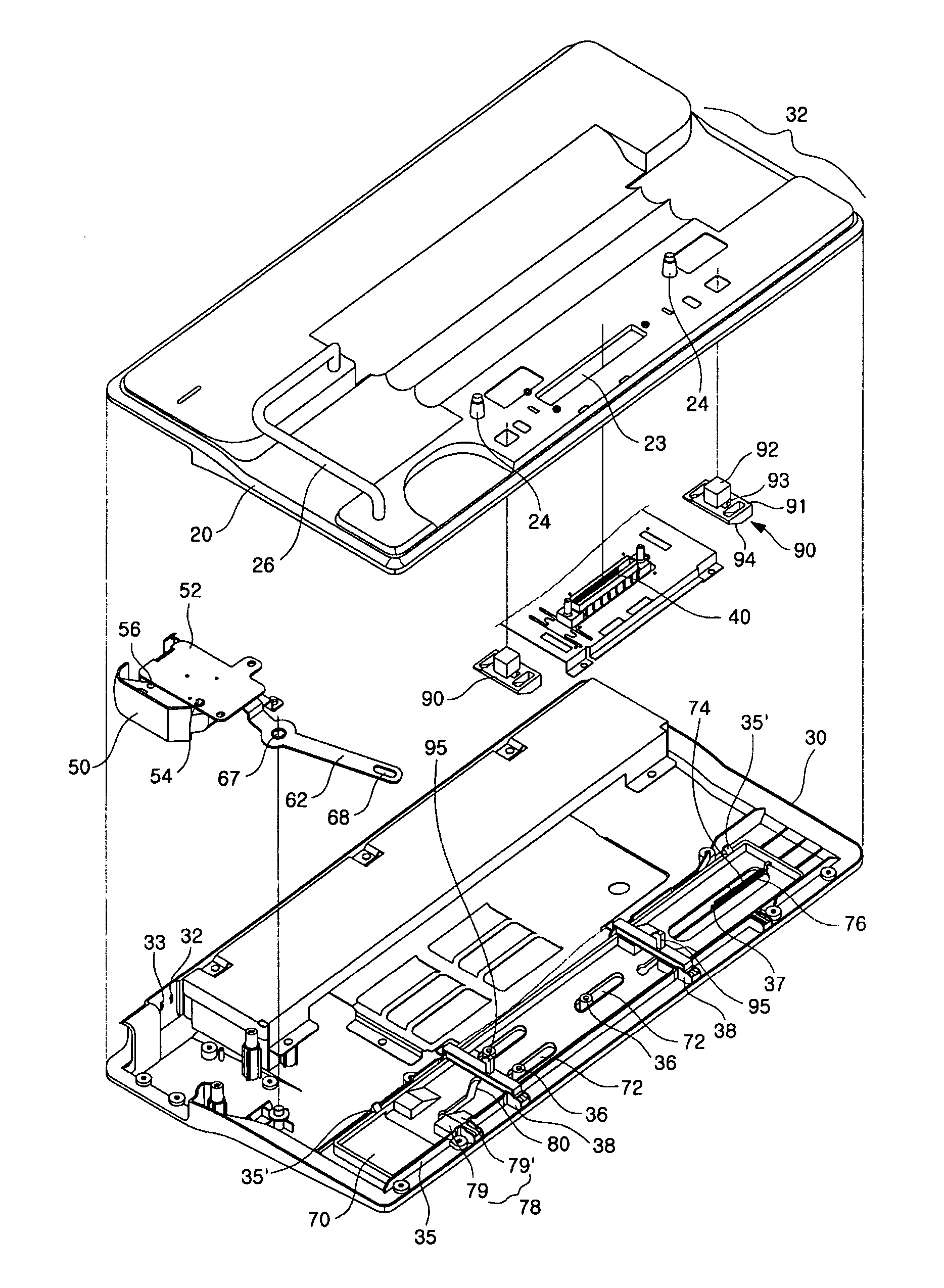
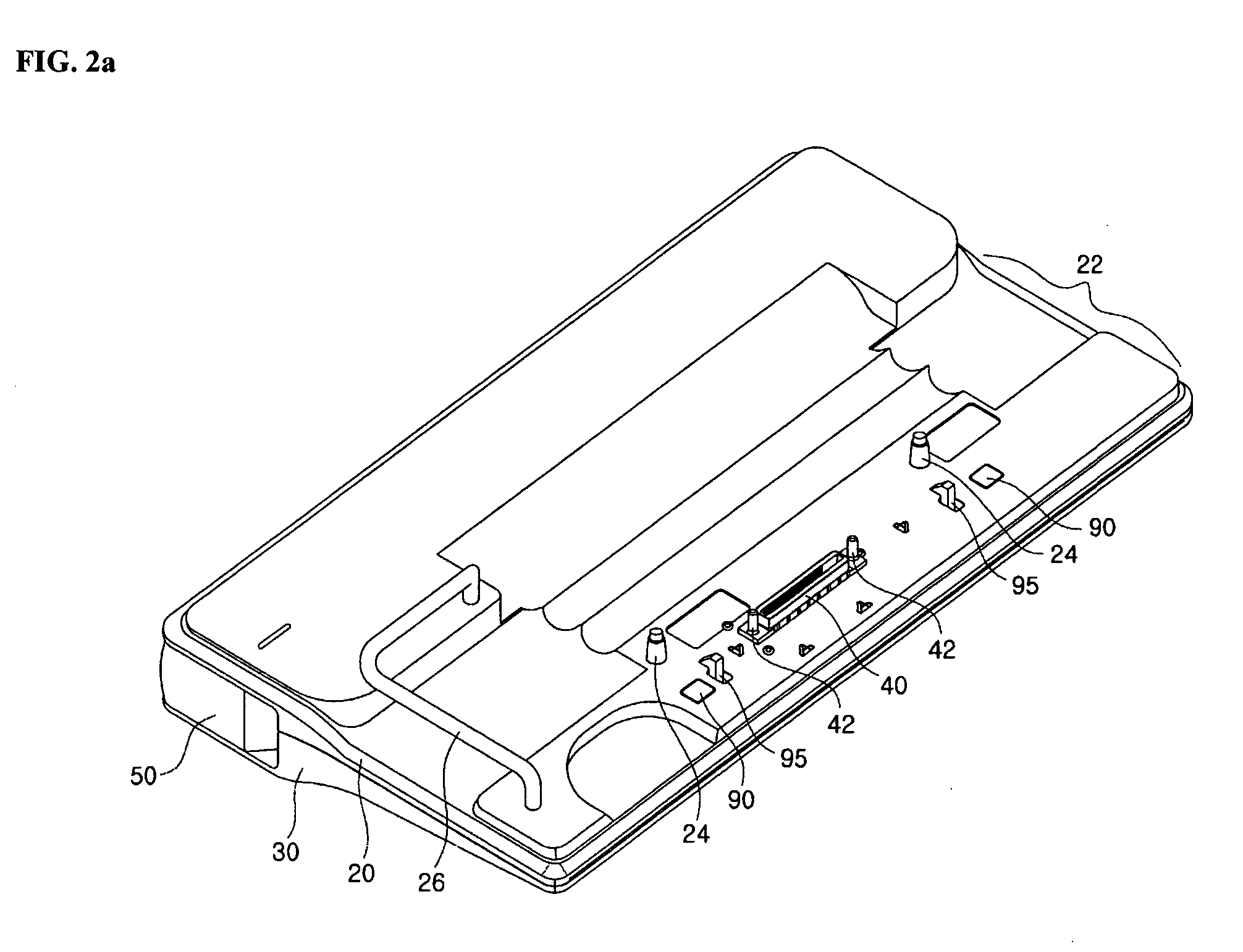
[0041]FIGS. 2a and 2b are perspective views showing an external appearance of the port replicator according to the present invention. FIG. 3 is an exploded perspective view showing the configuration of the port replicator, according to the present invention. FIG. 4 is a perspective view showing the configuration of moveable portions of an actuating lever and link mechanism, according to the present invention. FIGS. 5a and 5b show the configuration of a driving plate of the port replicator according to the present invention. FIG. 6 is a perspective view showing the configuration of catching hooks of the port replicator,...


PUM


Abstract

A port replicator includes upper and lower cases including a plurality of ports. An inclined supporting surface is formed with a connector for electrical connection with a computer at a front top surface of the cases. An actuating lever is provided at one side of the cases and receives an actuating force from a user. A link mechanism is provided within the cases. A driving plate is provided within the cases and includes at least one pair of cam slots and push cams and linearly moves in response to the actuating force transmitted via the link mechanism. A pair of catching hooks are guided along the cam slots and include a catching protrusion exposed from the top surface of the cases capable of catching a groove formed on a bottom surface of the computer. Push protrusions are guided by the push cams and selectively protrude beyond the top surface of the cases, thereby pushing up the bottom surface of the computer when the catching hooks are unfastened from the computer.

Description

[0001] This application claims the priority benefit of Patent Application No. 10-2004-0049054 filed on Jun. 28, 2004 in Republic of Korea, which is hereby incorporated by reference. BACKGROUND OF THE INVENTION [0002] 1. Field of the Invention [0003] The present invention relates to a port replicator, and more particularly, to a port replicator which can be mounted to a portable computer, such that the portable computer and peripheral devices can be more easily connected with each other. [0004] 2. Description of the Prior Art [0005] A port replicator is used to expand the function of a portable computer such as a notebook computer and includes a variety of connection ports. Such a port replicator allows only a portable computer to be separated and carried or used in a state where the portable computer is connected to the peripheral devices connected to the connection ports of the port replicator. [0006]FIG. 1 shows the configuration of a portable computer and port replicator, accordi...

Claims


Application Information

Patent Timeline
Patent Type & Authority Applications(United States)
IPC IPC(8): G06F1/16
CPCG06F1/1632Y10T70/5009G06F1/1613G06F1/1683G06F1/1684
Inventor KIM, YUN-TAE
Owner LG ELECTRONICS INC
Why Eureka
Try Eureka