Cam rotor internal combustion engine power system design method

A technology of internal combustion engine and power system, applied in the direction of internal combustion piston engine, combustion engine, machine/engine, etc., can solve the problems of limited expandability of triangular rotor internal combustion engine structure, difficulty in improving rotor shaft torque, and high processing requirements for core parts. Achieve the effects of short motion transmission link, easy automatic compensation, and large parameter range

Inactive Publication Date: 2017-06-20
DALIAN UNIV OF TECH
View PDF5 Cites 1 Cited by
  • Summary
  • Abstract
  • Description
  • Claims
  • Application Information

AI Technical Summary

Problems solved by technology

[0004] Although the triangular rotor engine has solved the problems of end face sealing and radial sealing, and has many outstanding advantages such as strong power, it still has high processing requirements for core parts, is too sensitive to wear, difficult to adjust compression ratio, and low thermal efficiency. The key problem is that the combustion efficiency is still difficult to improve
At the same time, similar to the piston internal combustion e

Method used


Image

  • Cam rotor internal combustion engine power system design method
  • Cam rotor internal combustion engine power system design method
  • Cam rotor internal combustion engine power system design method

Examples


Embodiment 1

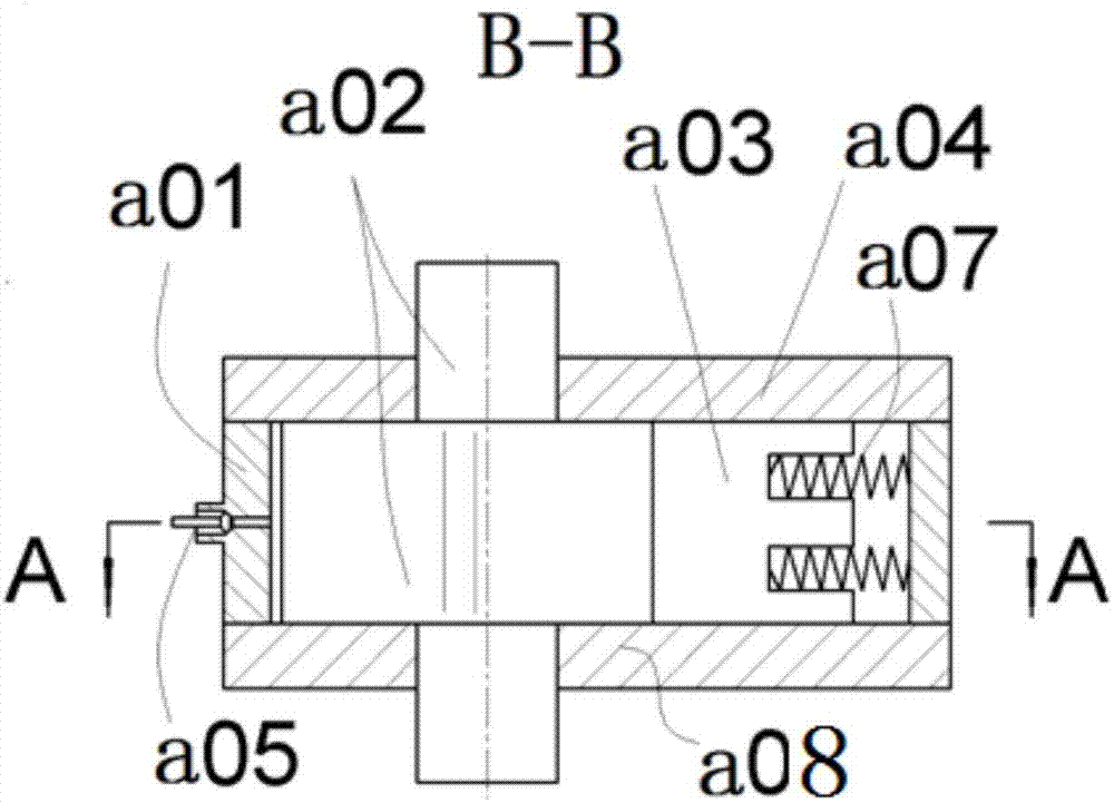
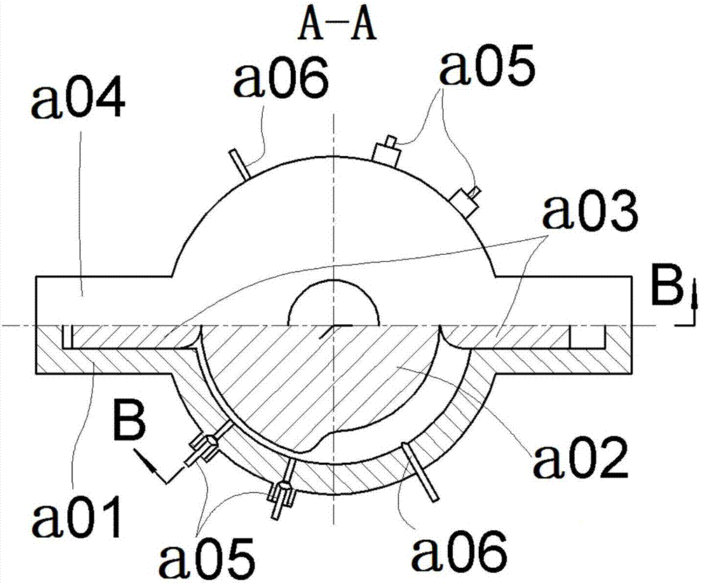
[0050] figure 1 is the basic structure diagram of a power system using this design method, and is also figure 2 Sectional view of B-B, figure 2 yes figure 1 A-A top view. The power system includes a rotor housing, a cam rotor, a direct moving slider, upper and lower end components, springs, valves and valve controllers; the inner cavity of the rotor housing a01 is cylindrical, and the cam rotor a02 is installed in the rotor housing a01, and the rotor housing The inner rotary surface of the cam rotor and the cam profile surface of the cam rotor form an annular gap with a change in the radial difference; the upper and lower end members a04 and a08 are respectively installed at both ends of the rotor chamber a01, and the lower end member a08 is connected to the rotor chamber a01 and the cam The rotor a02 constitutes the lower end seal; the upper end member a04 forms the upper end seal with the rotor housing a01 and the cam rotor a02; two springs a07 are installed in the inne...

Embodiment 2

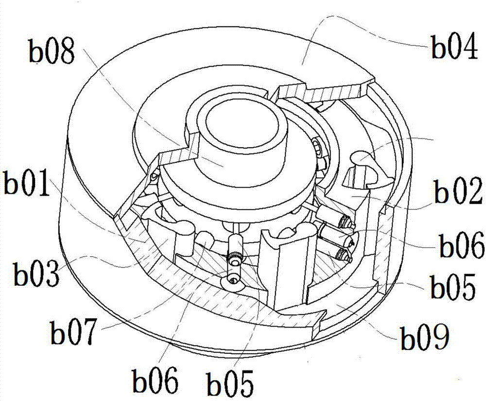
[0053] See image 3 , the combination of inner profile cam and inner cavity body components constitutes the outer rotor b01, the inner profile cam is a straight generatrix disc shape, has two sections of far resting section and near resting section, arranged symmetrically in the circumferential direction, and the arc length and centripetal angle of the far resting section are about 70°. The centripetal angles near the resting zone are about 90°. The outer slewing surface member is used as the central fixed frame b02 to install the cam follower pendulum block b03, and the number of pendulum blocks is evenly distributed. The pendulum block installation groove not only enables the pendulum block to swing on the fixed axis, but also forms an independent sealed cavity with the end member b04 , the compressed gas can be fed to make the pendulum block and the cam profile realize force sealing; the intake and exhaust ports b05 with valves, the fuel filling device b06, and the pendulu...

Embodiment 3

[0055] Figure 4A structure of a cam rotor internal combustion engine power system with the rotor inside and the output through the shaft is given. The rotor chamber c01 with a cylindrical inner cavity constitutes the frame, and the straight moving slider c03 is installed through the radial chute as the cam follower. The profile disc cam is combined into the rotor c02. The cam has two sections of far resting section and near resting area, which are arranged symmetrically in the circumferential direction. The arc length and centripetal angle of the far resting section are about 70°. The centripetal angles near the resting zone are about 90°. The slider groove and the end member c04 also form an independent sealed cavity, which can be fed with compressed air to make the pendulum block and the cam profile realize force sealing; the slider escapement c07 is set on the outer side of the chute, and the intake and exhaust ports with valves c05 , Ignition filling device c06, and sli...


PUM


Abstract

The invention belongs to the field of design of internal combustion engines and relates to a cam rotor internal combustion engine power system design method, in particular to a cam rotor internal combustion engine design method. In the design method, according to cam lift and size changes, caused by the cam lift, of the contour surface of a cam; other surfaces of the cam are wrapped through the inner surface of an inner cavity rotation surface component, the outer surface of an outer rotation surface component and corresponding end components in a contact sealing mode, and then an unsymmetrical annular gap is formed; the cam is made to do fixed-axis rotation along with one of the inner cavity component and the outer rotation surface component relative to the other one; a set of cam driven parts are mounted on the inner cavity component or the outer rotation surface which is not fixed to the cam. According to the design method, the four classic procedures of the otto cycle are realized through volume change, and the influence on the rotational speed is little. A control system is used in cooperation to realize flexible transformation of various working modes. The adaptability is high. The system is good in designability and especially suitable for being used in cooperation with computers to conduct flexible automatic control.

Description

technical field [0001] The invention belongs to the field of internal combustion engine design, and relates to a design method of a cam rotor internal combustion engine power system. Background technique [0002] The characteristic of the piston internal combustion engine is that the piston makes a reciprocating linear motion in the cylinder, and the output of the crankshaft rotary motion is realized through the crank slider mechanism. An Otto cycle is completed in the piston during two revolutions of the crankshaft. Since the four working processes of the Otto cycle of the piston internal combustion engine, intake, compression, combustion expansion, and exhaust correspond to four straight-line motions of the piston, they are called the intake stroke, compression stroke, power stroke, and exhaust stroke respectively. It is generally believed that the piston internal combustion engine has the advantages of high thermal efficiency, compact structure, strong mobility, and easy...

Claims


Application Information

Patent Timeline
IPC IPC(8): F02B53/00F02B53/04F02B55/02F02B53/02
CPCF02B53/00F02B53/02F02B53/04F02B55/02Y02T10/12
Inventor 孙守林卞永宁杨扬张光临洪鹏飞王琳
Owner DALIAN UNIV OF TECH
Why Eureka
Try Eureka