
Multifunctional reliable wall-hanging rack convenient and fast to use

A wall-mounted, multi-functional technology, applied in the field of wall-mounted racks, achieves the effects of extremely low production cost, obvious effect of popularization and use, and exquisite technical structure

Inactive Publication Date: 2017-06-20
LIUZHOU JINGYANG ENERGY SAVING TECH RES DEV
View PDF0 Cites 0 Cited by
  • Summary
  • Abstract
  • Description
  • Claims
  • Application Information

AI Technical Summary

Problems solved by technology

[0003] The purpose of the present invention is to provide a design technology with exquisite structure, multi-function, flexible and wide application, reliable, convenient and durable, extremely low manufacturing cost and better comprehensive cost performance, aiming at the technical defects of various existing common wall mount brackets and market product demand problems. The versatile, reliable and convenient wall mount

Method used


Image

  • Multifunctional reliable wall-hanging rack convenient and fast to use

Examples


Embodiment approach

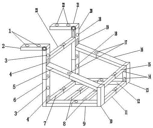
[0019] As shown in the accompanying drawings, the multifunctional, reliable and convenient wall mount of the present invention includes two parts, a main part and an accessory, and its main features are:

[0020] The main body includes a left fixed plate 2, a left inclined pipe 5, a left straight pipe 6, a rear bottom pipe 7, a middle bottom pipe 8, a left bottom pipe 9, a left front pipe 10, a front bottom pipe 11, a right bottom pipe 12, and a right front pipe 13. Front upper pipe 15, right inclined pipe 16, right straight pipe 20, right fixed plate 21, rear upper pipe 23,

[0021] One end of the left fixed plate 2 is articulated with the upper end of the left straight pipe 6, and its main function is to fold or fix the straight pipe body straight with the left straight pipe 6,

[0022] The upper end of the left inclined pipe 5 is placed in the left sleeve groove 4 and the lower end is placed in the sleeve groove on the upper side of the left front pipe 10. Its main function...


PUM


Abstract

The invention provides a multifunctional reliable wall-hanging rack convenient and fast to use. A left fixed plate is movably connected with the upper end of a left straight pipe. A left inclined pipe is arranged between a left sleeving groove and a front left pipe. The left straight pipe is arranged at the side far away from a right straight pipe. A bottom rear pipe is arranged between the left straight pipe and the right straight pipe. Bottom middle pipes are arranged between a bottom left pipe and a bottom right pipe. The bottom left pipe is arranged between the left straight pipe and the front left pipe. The front left pipe is arranged at the side far away from a front right pipe. A bottom front pipe is arranged at the lower end of the front left pipe and the lower end of the front right pipe. The bottom right pipe is arranged at the lower end of the front right pipe and the lower end of the right straight pipe. The front right pipe is arranged at the side far away from the front left pipe. An upper front pipe is arranged at the upper end of the front left pipe and the upper end of the front right pipe. A right inclined pipe is arranged at the upper side of a right sleeving groove and the upper side of the front right pipe. The right straight pipe is arranged at the side far away from the left straight pipe. A right fixed plate is movably connected with the upper end of the right straight pipe. An upper rear pipe is arranged at the upper side of the right straight pipe and the upper side of the left straight pipe. Left fixed holes are formed in the left fixed plate and a left fixing hole is formed in one side of the left straight pipe. The left sleeving pipe is formed at one side of the left straight pipe. Front sleeving grooves are formed in one side of the front right pipe. Positioning bolts are arranged in the left inclined pipe and the right inclined pipe. A right fixing hole is formed in one side of the right straight pipe. The right sleeving groove is formed in one side of the right straight pipe. Right fixed holes are formed in the right fixed plate.

Description

technical field [0001] The invention relates to a wall hanger, in particular to a multifunctional, reliable and convenient wall hanger. Background technique [0002] Although there are a lot of technical devices for wall-mounted brackets for various ordinary air conditioners, flushing water tanks, and other appliances, there are still disadvantages such as complicated technical structures, few functions, poor practicality, inconvenient installation and use, and high manufacturing costs. A simple, high-quality, flexible, practical, reliable, safe, convenient, cheap and durable wall mount bracket is needed. For this reason, it is necessary to invent a security door with a comprehensive technical structure that is simple, multi-functional, flexible and widely used, safe, reliable, convenient and extremely low in manufacturing cost. Contents of the invention [0003] The purpose of the present invention is to provide a design technology with exquisite structure, multi-functio...

Claims


Application Information

Patent Timeline
Patent Type & Authority Applications(China)
IPC IPC(8): F16M13/02F16M11/04
Inventor 韦战
Owner LIUZHOU JINGYANG ENERGY SAVING TECH RES DEV
Learn More