Foot pedal type engine oil collector

A collector and foot-operated technology, applied in the field of foot-operated oil collectors, can solve problems such as laborious, unfavorable collection, and excessive oil sample volume, and achieve simple assembly and disassembly, avoid deviation of test results, and low cost Effect

Inactive Publication Date: 2017-06-20
CHONGQING CHANGAN AUTOMOBILE CO LTD
View PDF4 Cites 0 Cited by
  • Summary
  • Abstract
  • Description
  • Claims
  • Application Information

AI Technical Summary

Problems solved by technology

[0003] There are usually two ways to collect engine oil. One method is to directly open the oil drain bolt of the oil pan to receive the oil. This method is easy to operate on the engine bench, but it cannot avoid the deviation of the test results caused by sampling. Leading to misjudgment problems; when collecting oil samples on the whole vehicle, a lift is required, and professional operators are required to operate related equipment, but the problem of deviation of test results due to sampling is still unavoidable
Another method is manual oil collection, the principle is to insert a hollow hose into the oil pan, the other end of the hose is connected to a container that can manually compress the internal space, and the air in the container is discharged by manually compressing the push rod, and then manually pulled back When pushing the rod, the oil in the oil pan is sucked into the container through the hose, but this method is very laborious in the actual operation process, and the amount of oil sample collected is not easy to be too much, which is not conducive to the collection of large sample volume

Method used


Image

  • Foot pedal type engine oil collector
  • Foot pedal type engine oil collector

Examples


Embodiment Construction

[0016] The present invention will be further described below according to the accompanying drawings.

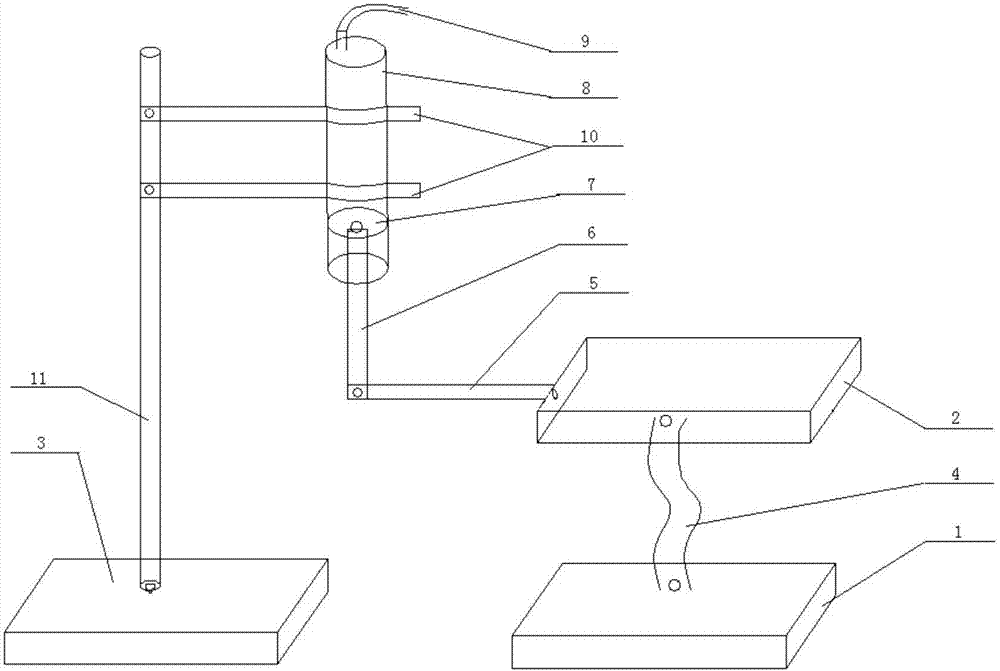
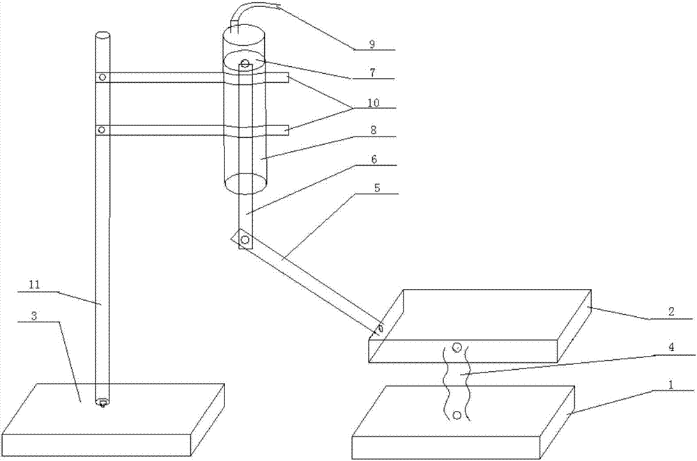
[0017] Such as figure 1 As shown, a foot-operated oil collector includes a first support plate 1 and a second support plate 3 located on the same horizontal plane, and the middle part above the second support plate 3 is fixedly connected to a vertical fixed rod 11, so The first support plate 1 is connected with the upper pedal 2 through the spring 4, and the side of the pedal 2 close to the fixed rod 11 is fixedly connected with one end of a horizontal connecting rod 5, and the other end of the connecting rod 5 is connected with a moving The lower end of the rod 6 is hinged by a bolt, and the upper end of the moving rod 6 is fixedly connected with a rubber stopper 7, and the rubber stopper 7 extends from the lower end of a sampling tube 8 and is interference fit with the sampling tube 8. The upper end of the pipe 8 is connected to one end of a hose 9 , and the other end of t...


PUM


Abstract

The invention relates to a foot pedal type engine oil collector. The foot pedal type engine oil collector comprises a first supporting plate and a second supporting plate, which are located on the same horizontal plane, wherein the middle of the upper surface of the second supporting plate is fixedly connected with a vertical fixed rod; the first supporting plate is connected with a pedal plate at the upper side through a spring; one side, close to the fixed rod, of the pedal plate is fixedly connected with one end of a horizontal connecting rod; the other end of the connecting rod is hinged to the lower end of a movable rod; the upper end of the movable rod is fixedly connected with a baffle; the baffle stretches into the lower end of a sampling pipe and is in interference fit with the sampling pipe; the upper end of the sampling pipe is connected with one end of a hose; the other end of the hose is inserted into an oil bottom shell; the sampling pipe is clamped on the fixed rod through a fixing clip. According to the foot pedal type engine oil collector provided by the invention, defects of a traditional manual sampling type sampling device that sampling needs more power in a sampling process and a sampling quantity is less can be avoided; meanwhile, a testing result deviation caused by the fact that collection is not proper can be avoided.

Description

technical field [0001] The invention relates to an oil collection device, in particular to a foot-operated oil collector. Background technique [0002] The engine is the heart of the car, and its various indicators directly affect the performance of the car; and the engine oil, as the blood of the engine, directly affects the performance of the engine and the service life of the engine. Changes in indicators are very important. [0003] There are usually two ways to collect engine oil. One method is to directly open the oil drain bolt of the oil pan to receive the oil. This method is easy to operate on the engine bench, but it cannot avoid the deviation of the test results caused by sampling. It leads to misjudgment problems; when collecting oil samples on the whole vehicle, a lift is required, and professional operators are required to operate related equipment, but the problem of deviation of test results due to sampling is still unavoidable. Another method is manual oil...

Claims


Application Information

Patent Timeline
Patent Type & Authority Applications(China)
IPC IPC(8): G01N1/14
CPCG01N1/14G01N2001/1418
Inventor 林海洪闻元邓伟祝洪宇孙宇良
Owner CHONGQING CHANGAN AUTOMOBILE CO LTD
Why Eureka
Try Eureka