Spatial positioning system and spatial location method

A space positioning and space position technology, applied in radio wave measurement system, electromagnetic wave re-radiation, utilization of re-radiation, etc., can solve the problems of tedious space positioning technology algorithm, high technical difficulty, inaccurate positioning, etc., and achieve the cost of computing hardware Inexpensive, easy technology implementation, accurate spatial positioning effect

Active Publication Date: 2017-06-20
PIMAX TECH SHANGHAI CO LTD
View PDF6 Cites 2 Cited by
  • Summary
  • Abstract
  • Description
  • Claims
  • Application Information

AI Technical Summary

Problems solved by technology

However, the camera-based spatial positioning technology has higher technical difficulties, and the data fusion of multiple cameras is also relatively cumbersome.
[0006] The existing spatial positioning technology algorithms are cumbersome and difficult to implement
Too many sensors are used, the data fusion is complicated, and the error is amplified, resulting in inaccurate positioning

Method used


Image

  • Spatial positioning system and spatial location method
  • Spatial positioning system and spatial location method
  • Spatial positioning system and spatial location method

Examples


no. 1 example

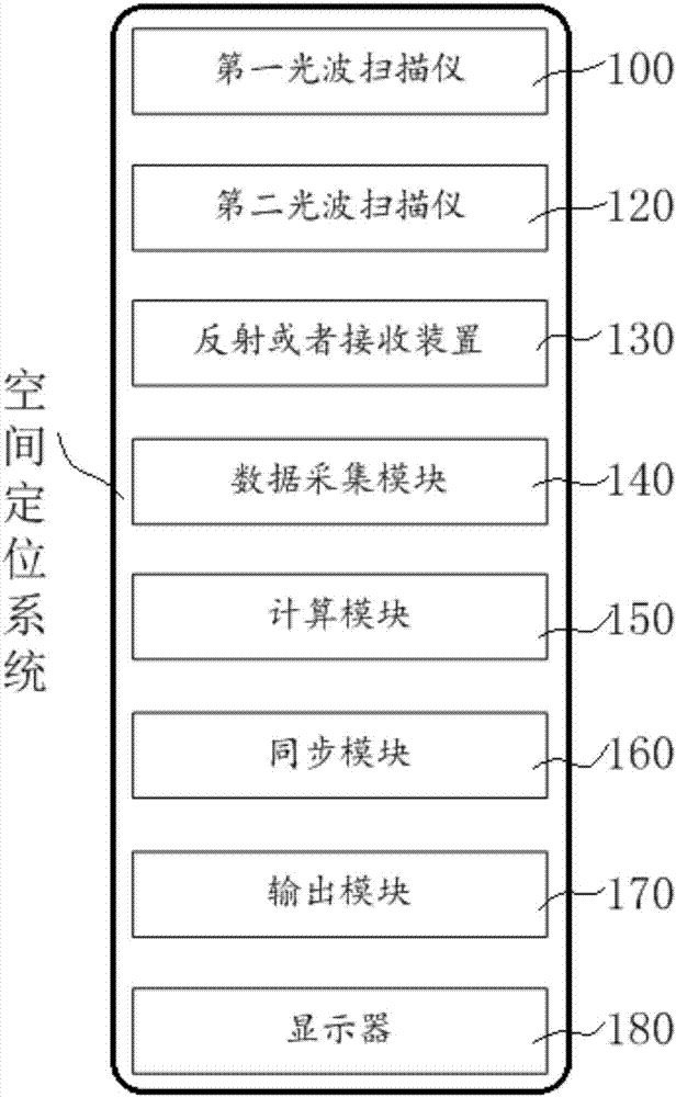
[0072] Such as figure 1 It is a block diagram of a space positioning system according to the first embodiment of the present invention: a space positioning system includes a first light wave scanner 100, a second light wave scanner 120, a reflecting or receiving device 130, a data acquisition module 140 and a calculation module 150,

[0073] The first optical wave scanner 100 scans the space around a first direction axis and scans the space 1000 around a second direction axis in sequence. The first direction axis (such as the Z axis) and the second direction axis (such as the X axis) axis) is a vertical relationship;

[0074] The second optical wave scanner 120 scans the space 1000 around a first direction axis (such as the Z axis) or a second direction axis (such as the X axis);

[0075] Keep a certain distance between the first light wave scanner 100 and the second light wave scanner 120;

[0076] The reflecting or receiving device 130, in the space 1000, sequentially ref...

no. 2 example

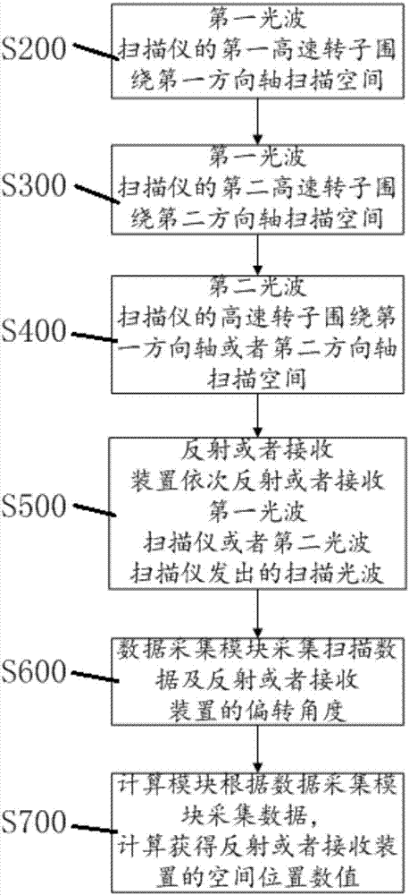
[0111] This embodiment also provides another new spatial positioning method, such as image 3 It is shown in the flowchart of the spatial positioning method of the second embodiment of the present invention:

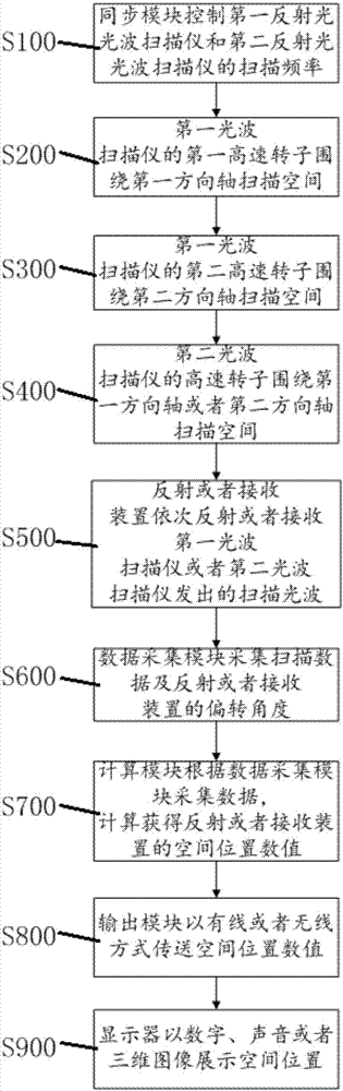
[0112] Further preferably, on the basis of the first embodiment, the spatial positioning method includes the following steps before step S200:

[0113] S100: The synchronization module controls scanning frequencies of the first light wave scanner and the second light wave scanner.

[0114] Further preferably, on the basis of the first embodiment, the spatial positioning method includes the following steps after step S700:

[0115] S800: The output module transmits the spatial position value in a wired or wireless manner;

[0116] S900: The display displays the spatial position values ​​in the form of numbers, sounds (broadcasting) or three-dimensional images.

no. 3 example

[0118] The embodiment discloses a three-side fixed-point spatial positioning system and method in virtual reality. The system includes a dual laser scanner 100, a single laser scanner 120, and a virtual reality head-mounted display 300. The schematic diagram of the system device is shown in Figure 4 It is shown in the schematic diagram of the space position arrangement of the space positioning system according to the third embodiment of the present invention (the diagonal arrangement of the double laser scanner 100 and the single laser scanner 120 in the space 1000 in the figure is only a schematic arrangement relationship, but It does not mean that there is and only such a placement relationship between them).

[0119] laser scanner 100, such as Figure 5 It is a schematic diagram of a dual laser scanner according to the third embodiment of the present invention, which includes two rotors 105 / 106 of a high-speed motor driving two laser emitters and an infrared LED lamp matr...


PUM


Abstract

The present invention discloses a spatial positioning system. The spatial positioning system comprises a first light wave scanner, a second light wave scanner, a reflecting or receiving device, a data acquisition module and a calculation module; the first light wave scanner scans a space around a first direction axis and scans the space around a second direction axis sequentially; the second light wave scanner scans the space around the first direction axis or the second direction axis; in the space, the reflecting or receiving device sequentially reflects or receives scanning light waves emitted by the first light wave scanner or the second light wave scanner; the data acquisition module acquires reflected light waves received by the first light wave scanner or the second light wave scanner, or acquires light waves received by the reflecting or receiving device; and the calculation module performs calculation according to the data acquired by the data acquisition module to obtain the spatial position numerical value of the reflecting or receiving device.

Description

technical field [0001] This patent application relates to the technical field of spatial positioning, and in particular to a virtual reality device and method for spatial positioning. Background technique [0002] Virtual reality technology is the key technology to support a comprehensive and integrated multi-dimensional information space that combines qualitative and quantitative, perceptual and rational knowledge. Virtual reality technology changes the computer from being good at processing digital single-dimensional information to being good at processing multi-dimensional information that people can feel and come into contact with in the process of thinking, in addition to digital information. In recent years, it has been very active in the field of VR technology research. Virtual reality is a higher level of multimedia technology development and a high-level integration and penetration of these technologies. It provides users with a more realistic experience, and provi...

Claims


Application Information

Patent Timeline
Patent Type & Authority Applications(China)
IPC IPC(8): G01S17/06
CPCG01S17/06
Inventor 翁建波
Owner PIMAX TECH SHANGHAI CO LTD
Why Eureka
Try Eureka