A spatial positioning system and a spatial positioning method
A technology of spatial positioning and spatial position, applied in radio wave measurement systems, instruments, measuring devices, etc., can solve the problems of complicated spatial positioning technology algorithms, inaccurate positioning, and high technical difficulties, and achieve low cost of computing hardware and accurate spatial positioning. , technology to achieve easy effect
- Summary
- Abstract
- Description
- Claims
- Application Information
AI Technical Summary
Problems solved by technology
Method used
Image
Examples
no. 1 example
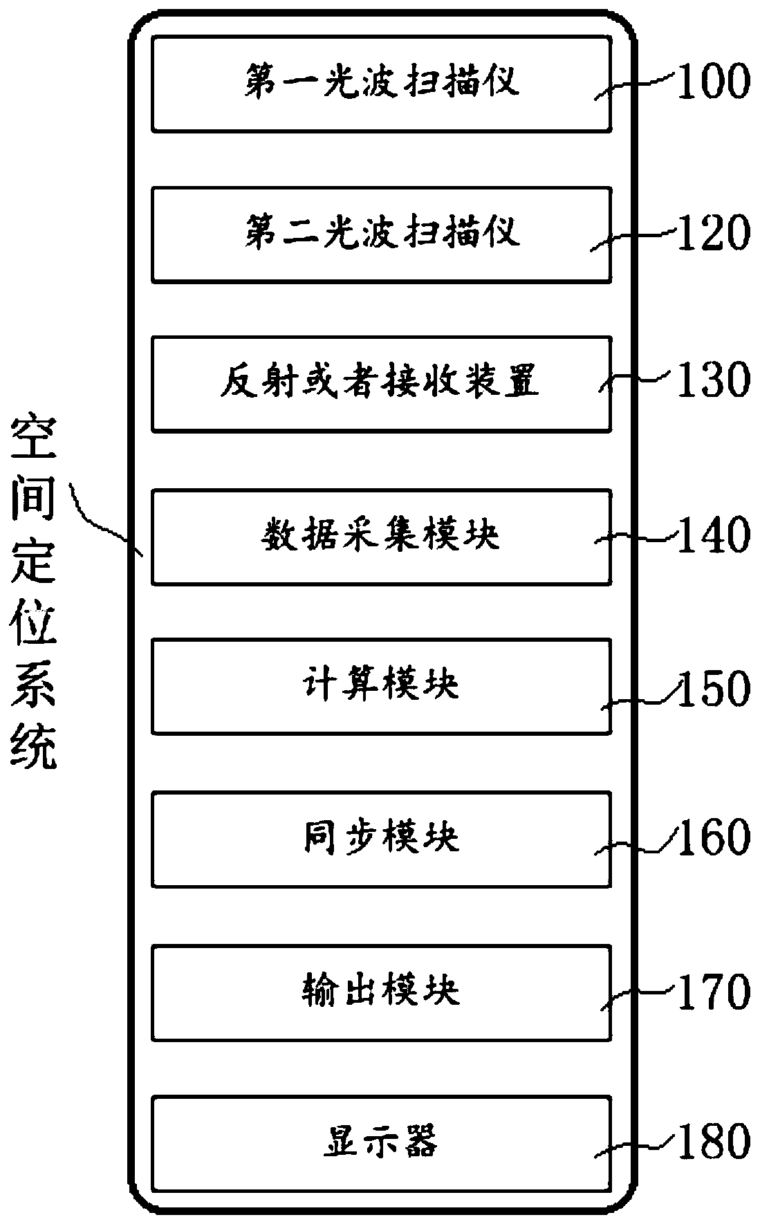
[0072] Such as figure 1 It is a block diagram of a space positioning system according to the first embodiment of the present invention: a space positioning system includes a first light wave scanner 100, a second light wave scanner 120, a reflecting or receiving device 130, a data acquisition module 140 and a calculation module 150,
[0073] The first optical wave scanner 100 scans the space around a first direction axis and scans the space 1000 around a second direction axis in sequence. The first direction axis (such as the Z axis) and the second direction axis (such as the X axis) axis) is a vertical relationship;
[0074] The second optical wave scanner 120 scans the space 1000 around a first direction axis (such as the Z axis) or a second direction axis (such as the X axis);
[0075] Keep a certain distance between the first light wave scanner 100 and the second light wave scanner 120;
[0076] The reflecting or receiving device 130, in the space 1000, sequentially ref...
no. 2 example
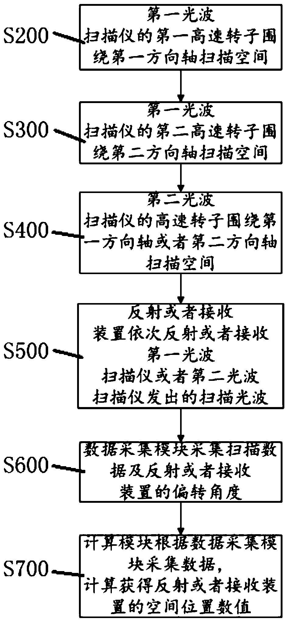
[0111] This embodiment also provides another new spatial positioning method, such as image 3 It is shown in the flowchart of the spatial positioning method of the second embodiment of the present invention:
[0112] Further preferably, on the basis of the first embodiment, the spatial positioning method includes the following steps before step S200:
[0113] S100: The synchronization module controls scanning frequencies of the first light wave scanner and the second light wave scanner.
[0114] Further preferably, on the basis of the first embodiment, the spatial positioning method includes the following steps after step S700:
[0115] S800: The output module transmits the spatial position value in a wired or wireless manner;
[0116] S900: The display displays the spatial position values in the form of numbers, sounds (broadcasting) or three-dimensional images.
no. 3 example
[0118] The embodiment discloses a three-side fixed-point spatial positioning system and method in virtual reality. The system includes a dual laser scanner 100, a single laser scanner 120, and a virtual reality head-mounted display 300. The schematic diagram of the system device is shown in Figure 4 It is shown in the schematic diagram of the space position arrangement of the space positioning system according to the third embodiment of the present invention (the diagonal arrangement of the double laser scanner 100 and the single laser scanner 120 in the space 1000 in the figure is only a schematic arrangement relationship, but It does not mean that there is and only such a placement relationship between them).
[0119] laser scanner 100, such as Figure 5 It is a schematic diagram of a dual laser scanner according to the third embodiment of the present invention, which includes two rotors 105 / 106 of a high-speed motor driving two laser emitters and an infrared LED lamp matr...
PUM
 Abstract
Description
Claims
Application Information
 - R&D
- Intellectual Property
- Life Sciences
- Materials
- Tech Scout
- Unparalleled Data Quality
- Higher Quality Content
- 60% Fewer Hallucinations
Browse by: Latest US Patents, China's latest patents, Technical Efficacy Thesaurus, Application Domain, Technology Topic, Popular Technical Reports.
© 2025 PatSnap. All rights reserved.Legal|Privacy policy|Modern Slavery Act Transparency Statement|Sitemap|About US| Contact US: help@patsnap.com


