
Metal bridge transducer element and manufacturing method thereof

A manufacturing method and metal bridge technology, applied in the direction of offensive equipment, blasting barrels, weapon accessories, etc., can solve the problems of the influence of the metal bridge electric explosive device on the reliability, high decisiveness, and low production efficiency of the metal bridge electric explosive device. Artificial interference, to ensure the effect of accurate alignment

Active Publication Date: 2018-12-25
INST OF CHEM MATERIAL CHINA ACADEMY OF ENG PHYSICS
View PDF11 Cites 0 Cited by
  • Summary
  • Abstract
  • Description
  • Claims
  • Application Information

AI Technical Summary

Problems solved by technology

[0003] The traditional manufacturing method of metal bridge electric explosive devices adopts the method of mechanical processing and manual precision assembly. On the one hand, the process of this method is relatively complicated, and the cost of raw materials and labor costs are high, which ultimately leads to the production efficiency of metal bridge electric explosive devices. Low cost and high cost; on the other hand, in the assembly process, it is necessary to ensure that the center bridge area of ​​the metal bridge is accurately aligned with the inner hole of the acceleration chamber, and it is also necessary to ensure that the substrate, metal bridge, flyer, acceleration chamber and charge In close contact in the axial direction
The process is disturbed and decisive by human factors, which will have a certain impact on ensuring the reliability of the metal bridge electric explosion device.

Method used


Image

  • Metal bridge transducer element and manufacturing method thereof
  • Metal bridge transducer element and manufacturing method thereof
  • Metal bridge transducer element and manufacturing method thereof

Examples


Embodiment 1

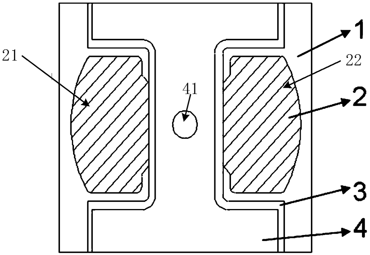
[0027] image 3 It is a schematic diagram of the structure and principle of the metal bridge transducer element provided by Embodiment 1 of the present invention. like image 3 As shown, the metal bridge transducer includes a substrate 1, a metal bridge layer 2 formed by adding metal materials on the surface of the substrate 1 through additive manufacturing technology, and passing through a part of the metal bridge layer 2 and a part of the substrate 1. The additive manufacturing technology increases the flying sheet layer 3 formed of non-metallic materials, and the accelerating chamber layer 4 formed of non-metallic materials is added on the flying sheet layer 3 through additive manufacturing technology. Specifically, the substrate 1 is a ceramic substrate or a glass-ceramic substrate, and the existing ceramic substrate products in the market can be directly used, or the ceramic substrate can be formed by using additive technology to obtain the substrate. The metal material...

Embodiment 2

[0032] Embodiment 2 is a manufacturing method of a metal bridge transducer, the method comprising the following steps:

[0033] Step (1), using acetone and deionized water to treat the surface of the substrate 1 through a standard cleaning process.

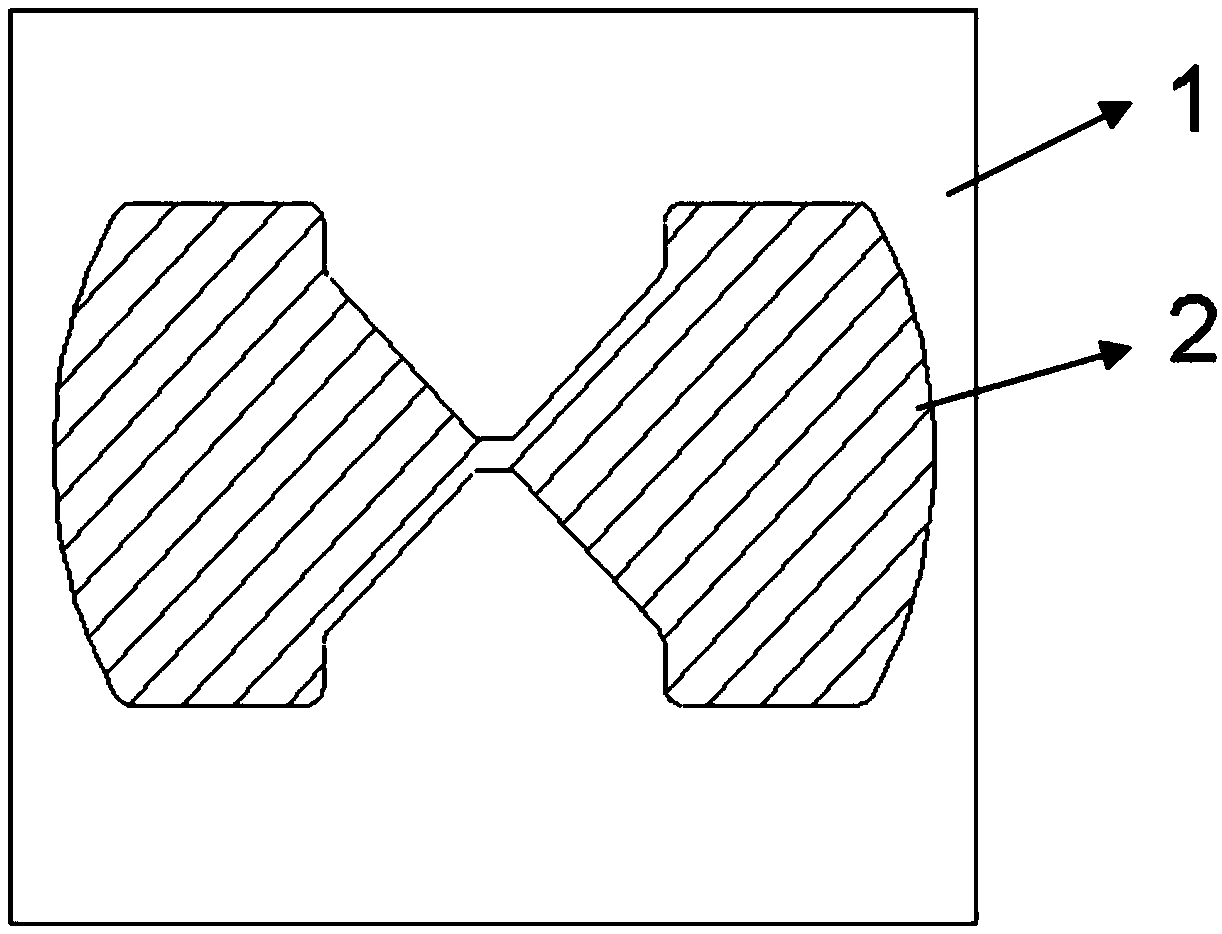
[0034] Step (2), such as figure 1 shown, according to figure 1 The shape of the metal bridge layer 2 in the metal bridge layer 2 is formed by additive manufacturing of the metal bridge shape on the surface of the substrate 1 . In this embodiment, the center part of the shape of the metal bridge is square, the length and width are 0.8 mm, and the thickness is 8 μm. In actual use, metal bridge shapes of other sizes can also be manufactured by additive technology. The size of the metal bridge can be are other sizes.

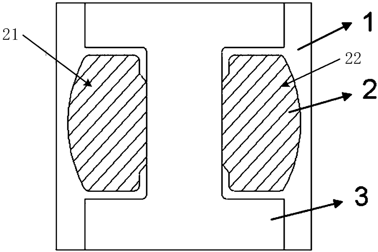
[0035] Step (3), such as figure 2 As shown, the non-metallic parylene material is added by additive manufacturing technology on a part of the metal bridge layer 2 and a part of the substrate 1 to form a flyer layer...


PUM

PropertyMeasurementUnit
thicknessaaaaaaaaaa
thicknessaaaaaaaaaa
thicknessaaaaaaaaaa

Abstract

The invention relates to a metal bridge electric explosion device, and provides a metal bridge energy conversion component and a manufacturing method of the metal bridge energy conversion component. The metal bridge energy conversion component comprises a substrate, a metal bridge layer, a fly die layer and an accelerating chamber layer. The metal bridge layer is formed on the surface of the substrate and made of metal materials in an additive mode through an additive manufacturing technology. The fly die layer is formed on the partial region of the metal bridge layer and the partial region of the substrate and made of non-metal materials in an additive mode through the additive manufacturing technology. The accelerating chamber layer is formed on the fly die layer and made of non-metal materials in an additive mode through the additive manufacturing technology, and a small hole is formed in the center area of the accelerating chamber layer. The region, without being covered with non-metal materials, of the metal bridge layer serves as an electrode of the metal bridge energy conversion component. According to the technical scheme, the structures of various layers of the metal bridge energy conversion component are formed through the additive technology, layered structures of core components of the metal bridge electric explosion device are formed in a sequential forming mode, and therefore man-made interference in the manufacturing process is eliminated, and accurate alignment of various components and close attachment of various layers are guaranteed.

Description

technical field [0001] The invention belongs to the field of metal bridge electric explosion devices, and in particular relates to a metal bridge transducer element and a manufacturing method thereof. Background technique [0002] The metal bridge electric explosion device may be detonated only in a specific discharge circuit and the voltage is greater than 500V. It will not have unexpected effects under the action of human body static electricity, static electricity generated by weapon systems and stray currents. It is a kind of High safety and high reliability pyrotechnics. The metal bridge electric explosive device is generally composed of a substrate, a metal bridge, a flyer, an accelerating chamber, and a charge, among which the metal bridge transducer element composed of the substrate, metal bridge, flying piece and accelerating chamber is the core of the metal bridge electric explosive device. Core components. In recent years, the low energy, integration and low cos...

Claims


Application Information

Patent Timeline
Patent Type & Authority Patents(China)
IPC IPC(8): F42B3/12F42B3/195
CPCF42B3/124F42B3/195
Inventor 吕军军王万军郭菲付秋菠
Owner INST OF CHEM MATERIAL CHINA ACADEMY OF ENG PHYSICS
Learn More