A Design Method of Aeroengine Acceleration Control Law

An aero-engine and acceleration control technology, which is applied in the direction of engine control, machine/engine, mechanical equipment, etc., can solve the problems of small application range, poor engineering adaptability, and high cost, and achieve the effect of saving costs and improving engineering adaptability

Active Publication Date: 2019-03-22
AECC SHENYANG ENGINE RES INST
View PDF6 Cites 0 Cited by
  • Summary
  • Abstract
  • Description
  • Claims
  • Application Information

AI Technical Summary

Problems solved by technology

[0003] The main disadvantages of existing aero-engine acceleration control laws are as follows: first, the scope of application is small, such as the first and second schemes are not suitable for engines with drastic changes in flight conditions; second, the fuel supply to the main combustion chamber is the direct control target, This requires accurate control of the fuel supply to the main combustion chamber in order to meet the acceleration time requirements; third, it is necessary to carry out a large number of machine tests to obtain the optimal control law, and the cost is high; fourth, it cannot better adapt to the individual engine It is necessary to adjust the acceleration control law according to the actual situation of each engine to ensure that the requirements of the acceleration time index are met, and the engineering adaptability is not strong

Method used


Image

  • A Design Method of Aeroengine Acceleration Control Law
  • A Design Method of Aeroengine Acceleration Control Law
  • A Design Method of Aeroengine Acceleration Control Law

Examples


Embodiment Construction

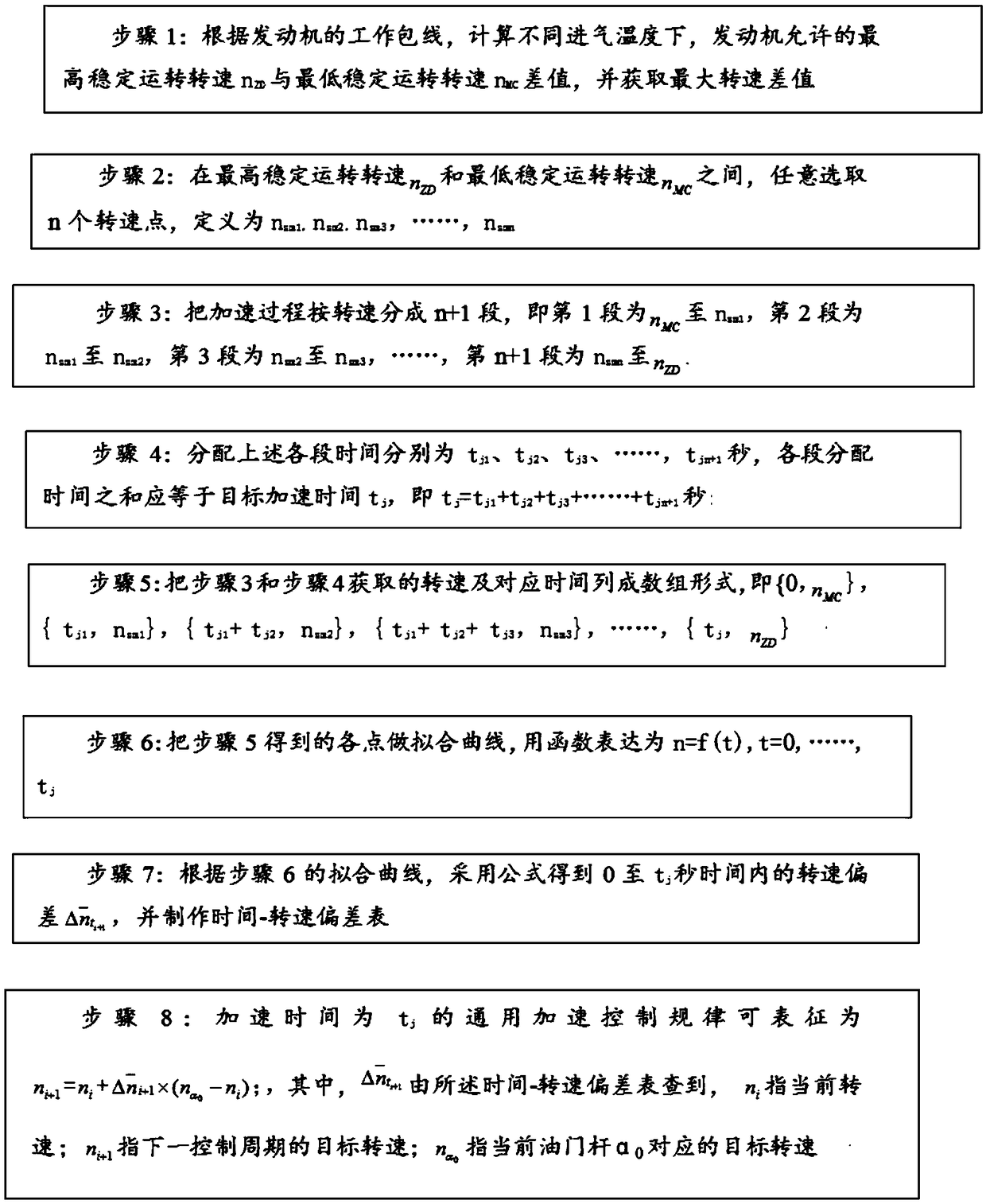
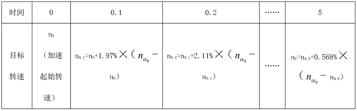
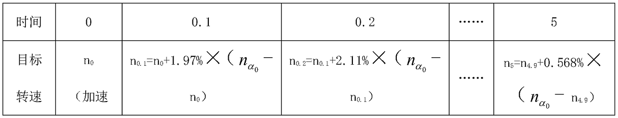
[0026] To make the objectives, technical solutions, and advantages of the implementation of the present invention clearer, the technical solutions in the embodiments of the present invention will be described in more detail below in conjunction with the accompanying drawings in the embodiments of the present invention. In the drawings, the same or similar reference numerals indicate the same or similar elements or elements with the same or similar functions. The described embodiments are part of the embodiments of the present invention, rather than all of the embodiments. The embodiments described below with reference to the accompanying drawings are exemplary, and are intended to explain the present invention, but should not be construed as limiting the present invention. Based on the embodiments of the present invention, all other embodiments obtained by those of ordinary skill in the art without creative work shall fall within the protection scope of the present invention. ...


PUM


Abstract

The invention discloses a design method of an aero-engine acceleration control rule. The design method of the aero-engine acceleration control rule comprises the following steps: 1, obtaining the maximum rotating speed difference value; 2, randomly selecting n rotating speed points between the highest stable operation rotating speed and the lowest stable operation rotating speed; 3, dividing an acceleration process into n+1 stages according to the rotating speeds; 4, distributing tj1, tj2, tj3, and the like, tj(n+1) to all the stages; 5, listing the rotating speeds and the corresponding time points which are obtained in the step 3 and the step 4 into arrays; 6, fitting a curve through all points obtained in the step 5; 7, obtaining a rotating speed deviation within a time period from 0 to tj; and 8, showing the universal acceleration control rule at the acceleration time of tj as follows: shown in the specification. The design method of the aero-engine acceleration control rule has the advantage that a method for not taking the oil supply amount of a main combustion chamber as a control target is adopted, so that the dependency of an acceleration process on the control accuracy of the oil supply amount of the main combustion chamber is reduced.

Description

Technical field [0001] The invention relates to the technical field of aeroengines, in particular to a design method of aeroengine acceleration control law. Background technique [0002] The current aero-engine acceleration control law is based on the fuel supply of the main combustion chamber as the dependent variable. The independent variables are slightly different. There are three main types: one is W f =f(t), that is, control the fuel supply of the main combustion chamber according to time; the other is W f =f(P 3 ), that is, control the fuel supply of the main combustion chamber according to the compressor outlet pressure; the third is That is, the fuel supply of the main combustion chamber is controlled according to the converted engine speed. [0003] The main disadvantages of the existing aero-engine acceleration control law are: first, the application range is small. For example, the first and second schemes are not suitable for engines with drastically changing flight co...

Claims


Application Information

Patent Timeline
Patent Type & Authority Patents(China)
IPC IPC(8): F02C9/00
CPCF02C9/00F05D2270/04F05D2270/708
Inventor 刘亚君吉思环韩文俊李焦宇赵明阳
Owner AECC SHENYANG ENGINE RES INST
Why Eureka
Try Eureka