
Eureka
For R&D, Eureka makes reading and utilizing patents & technical documents easy.
Eureka AIR
Designed for self-driven R&D workflows. Generate viable solutions, solve complex R&D challenges, empower your innovation with AI.

Eureka Materials
Designed for material experts only. Revolutionize your material R&D, from search, analyze, to developing new materials.

TechResearch
Generate reliable direction feasibility study reports for your R&D in just a few steps.

TechSeek
Discover and master advanced knowledge NOW. Basics, ideas, possibilities, all at once.

TechMind
As an expert in R&D Theories, TechMind can generates customized viable solutions instantly.

TechRisk
Analyze your overall solution with one click, know your potential R&D risks in advance.

TechMonitor
Get weekly tech updates, stay abreast of the latest tech innovations and key insights.
Electrical switching apparatus comprising a switching mechanism and at least one auxiliary module
A technology of auxiliary modules and electrical switches, which is applied in the direction of protection switch operation/release mechanism, switches activated by overcurrent and other abnormal electrical conditions, components of protection switches, etc., and can solve problems such as suboptimal technology
- Summary
- Abstract
- Description
- Claims
- Application Information
AI Technical Summary
Problems solved by technology
Method used
Image

Examples
Embodiment Construction
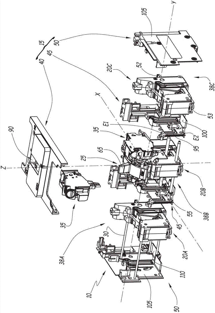
[0031] The electrical switching apparatus 10 comprises a housing 15, a first switch member 20A, a second switch member 20B, a third switch member 20C, a control mechanism 25 for each switch member 20A, 20B, 20C, a mechanical reference member 30 and at least one Auxiliary module 35.
[0032] The switching device 10 is adapted to receive a first current via an input electrical conductor and deliver the first current to an output electrical conductor, and vice versa.
[0033] Preferably, the switching device 10 is adapted to receive a plurality of first currents through several input conductors, and to deliver each first current to a respective output conductor. exist figure 1 In , the switchgear 10 is a three-phase circuit breaker.
[0034] For the switchgear 10 there is a defined vertical direction Z, transverse direction Y and longitudinal direction X. Each of the vertical direction Z, the lateral direction Y, and the longitudinal direction X is at right angles to the other...
PUM
 Abstract
Description
Claims
Application Information
 - R&D Engineer
- R&D Manager
- IP Professional
- Industry Leading Data Capabilities
- Powerful AI technology
- Patent DNA Extraction
Browse by: Latest US Patents, China's latest patents, Technical Efficacy Thesaurus, Application Domain, Technology Topic, Popular Technical Reports.
© 2024 PatSnap. All rights reserved.Legal|Privacy policy|Modern Slavery Act Transparency Statement|Sitemap|About US| Contact US: help@patsnap.com