

Uplink control channel transmitting method and device
A technology of a control channel and a transmission method, which is applied in the field of an uplink control channel transmission method and device, can solve problems such as extended feedback time in a TDD system, and achieve the effect of reducing feedback delay
- Summary
- Abstract
- Description
- Claims
- Application Information
AI Technical Summary
Problems solved by technology
Method used
Image


Examples
Embodiment 1
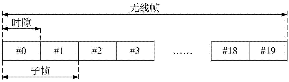
[0117] Optional Embodiment 1 of the present invention provides an uplink control channel transmission method with uplink and downlink subframe configuration 2. For uplink and downlink subframe configuration 2, 2 uplink subframes (U subframes) feed back 8 downlink subframes (D subframes). ) (including downlink pilot time slots (DwPTS) in 2 special subframes (S subframes)), Figure 8 It is a schematic diagram of the feedback timing interval of each subframe when k≥2 according to the uplink and downlink subframe configuration 2 of an optional embodiment of the present invention without adding feedback resources. The feedback timing interval of each subframe is as follows Figure 8 As shown, the average k value at this time is 3.75, and the average time delay of a one-way RTT is 5.75.
[0118] Figure 9 It is a schematic diagram of the feedback timing interval of each subframe when k≥2 when the uplink and downlink subframe configuration 2 in the special subframe is added as the f...
Embodiment 2
[0125] Optional Embodiment 1 of the present invention provides an uplink control channel transmission method with uplink and downlink subframe configuration 3. For uplink and downlink subframe configuration 3, 3 uplink subframes feed back 7 downlink subframes (including 1 special subframe) DwPTS), Figure 11 It is a schematic diagram of the feedback timing interval of each subframe when k≥2 according to the uplink and downlink subframe configuration 3 of an optional embodiment of the present invention without adding feedback resources, and the feedback timing interval of each subframe is as follows Figure 11 As shown, the average k value at this time is 4.86, and the one-way average delay of one RTT is 7.28.
[0126] Figure 12 It is a schematic diagram of the feedback timing interval of each subframe when k≥2 when the uplink and downlink subframe configuration 3 in the special subframe is added as the feedback resource according to the optional embodiment of the present inv...
Embodiment 3
[0131]Optional Embodiment 1 of the present invention provides an uplink control channel transmission method with uplink and downlink subframe configuration 4. For uplink and downlink subframe configuration 4, 2 uplink subframes feed back 8 downlink subframes (including 1 special subframe) DwPTS), Figure 14 It is a schematic diagram of the feedback timing interval of each subframe when k≥2 according to the uplink and downlink subframe configuration 4 of an optional embodiment of the present invention without adding feedback resources. The feedback timing interval of each subframe is as follows Figure 14 As shown, the average k value at this time is 5, and the one-way average delay of one RTT is 7.
[0132] Figure 15 It is a schematic diagram of the feedback timing interval of each subframe when k≥2 when the uplink and downlink subframe configuration 4 in the special subframe is added as a feedback resource according to an optional embodiment of the present invention, as sho...
PUM
 Abstract
Description
Claims
Application Information