
Clamping method of tube workpiece clamp

The technology of a workpiece fixture and clamping method is applied in the direction of clamping devices, manufacturing tools, metal processing machinery parts, etc., which can solve the problems of manpower tightening and damage to objects, so as to ensure accurate clamping and avoid virtual contact or clamping force Insufficient effect

Inactive Publication Date: 2017-06-30
SUZHOU YASIKE PRECISION CNC CO LTD
View PDF9 Cites 9 Cited by
  • Summary
  • Abstract
  • Description
  • Claims
  • Application Information

AI Technical Summary

Problems solved by technology

However, this kind of clamp requires manpower to tighten, and the force is too large to damage the clamped items

Method used


Image

  • Clamping method of tube workpiece clamp
  • Clamping method of tube workpiece clamp
  • Clamping method of tube workpiece clamp

Examples


Embodiment Construction

[0038] The technical solution of the present invention will be described in more detail below in conjunction with specific embodiments and accompanying drawings.

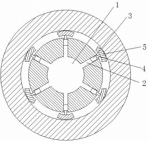
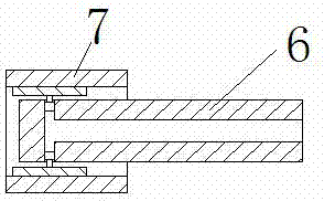
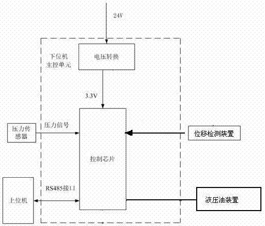
[0039] Such as figure 1 As shown, a fixture clamping method for pipe workpieces, the fixture includes a connecting shaft, a hydraulic oil device, a hydraulic diameter expanding mechanism, a displacement detection device, a pressure detection device and a host computer, wherein one end of the connecting shaft is connected to the machine tool The main shaft is connected, and the other end of the connecting shaft is evenly equipped with multiple hydraulic diameter expanding mechanisms along the circumference of the connecting shaft on the same plane, and the multiple hydraulic expanding mechanisms are supported on the inner side wall of the workpiece to support and clamp the workpiece; A main oil passage and several oil passage units connected with the main oil passage are provided in the axial direction of the connect...


PUM


Abstract

The invention discloses a clamping method for a pipe workpiece fixture. The clamp includes a connecting shaft, a hydraulic oil device, a hydraulic diameter expanding mechanism, a displacement detecting device, a pressure detecting device and a host computer, wherein one end of the connecting shaft is connected to the The machine tool spindle is connected, and the other end of the connecting shaft is evenly provided with multiple hydraulic diameter expanding mechanisms along the circumference of the connecting shaft on the same plane. The multiple hydraulic expanding mechanisms are supported on the inner wall of the workpiece to support and clamp the workpiece. The invention clamps the workpiece through several hydraulic diameter expanding mechanisms, and detects the workpiece through double detection mechanisms to ensure accurate clamping of the workpiece.

Description

technical field [0001] The invention relates to a clamping method for a pipe workpiece fixture. Background technique [0002] Machine tool fixtures can be divided into the following categories according to specialized classification: [0003] 1. General fixture. Universal fixtures refer to fixtures that have been standardized and can be used to process different workpieces within a certain range. For example, three-jaw chucks and four-jaw single-action chucks on lathes, vises, dividing heads, and rotary tables on milling machines. Such fixtures are generally produced by professional factories and are often provided to users as machine tool accessories. It is characterized by wide adaptability and low production efficiency, and is mainly suitable for single-piece and small-batch production. [0004] 2. Special fixture. Special fixtures refer to fixtures specially designed for a certain process of a certain workpiece. It is characterized by compact structure, fast, conve...

Claims


Application Information

Patent Timeline
Patent Type & Authority Applications(China)
IPC IPC(8): B23Q3/12B23Q17/00
CPCB23Q3/12B23Q17/005B23Q2703/10
Inventor 马峻孙建明
Owner SUZHOU YASIKE PRECISION CNC CO LTD
Learn More