Marine organism hazardous substance detection weighing device

A technology for marine organisms and harmful substances, which is used in measuring devices, weighing equipment for materials with special properties/forms, weighing, etc. To achieve the effect of improving weighing efficiency

Active Publication Date: 2017-06-30
ZHEJIANG MARICULTURE RES INST
2 Cites 3 Cited by

AI-Extracted Technical Summary

Problems solved by technology

[0003] The existing way to detect harmful substances in the ocean is to select marine organisms, then crush the marine organisms, then select a certain weight of powder, and then detect the harmful substances in the powder, so as to detect harmful substances in marine organisms The proportion of the proportion, and then calculate the pollution of the ocean at this time. However, the existing way to weigh the powder of marine organisms is to first place the powder of marine organisms in a beaker, and then place the powder on the balance that needs to be weighed. Then use tweezers to clamp the powder of marine org...

Abstract

The present invention discloses a marine organism hazardous substance detection weighing device. The device comprises an unloading mechanism for accommodating marine organism powder and a weighing mechanism arranged below the unloading mechanism; the unloading mechanism comprises a storage hopper for storing the marine organism powder, and a rationed feeding device arranged in the storage funnel; a tray is arranged below the material outlet of the storage hopper; and the rationed feeding device transfers the marine organism powder in the storage hopper to the tray from the material outlet in a rationed manner. According to the marine organism hazardous substance detection weighing device of the invention, the rationed feeding device arranged in the unloading mechanism, so that rationed powder can be transferred onto the weighing mechanism at one time, the accurate weighing of the powder can be realized effectively through the feedback effect of the weighing mechanism, and therefore, the efficiency of weighing can be greatly improved.

Application Domain

Technology Topic

EngineeringHazardous substance +2

Image

  • Marine organism hazardous substance detection weighing device
  • Marine organism hazardous substance detection weighing device
  • Marine organism hazardous substance detection weighing device

Examples

  • Experimental program(1)

Example Embodiment

[0016] The present invention will be described in further detail below in conjunction with the embodiments given in the accompanying drawings.
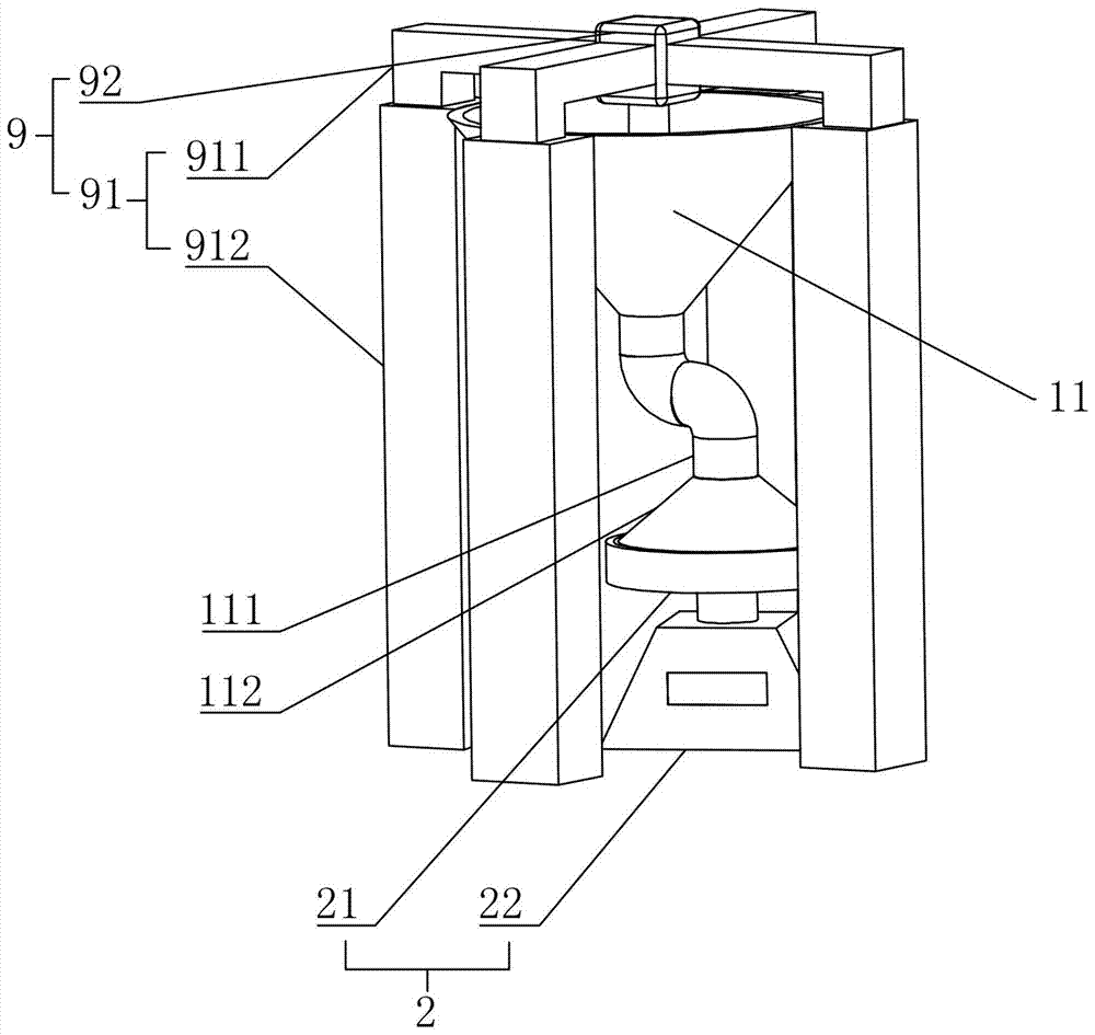
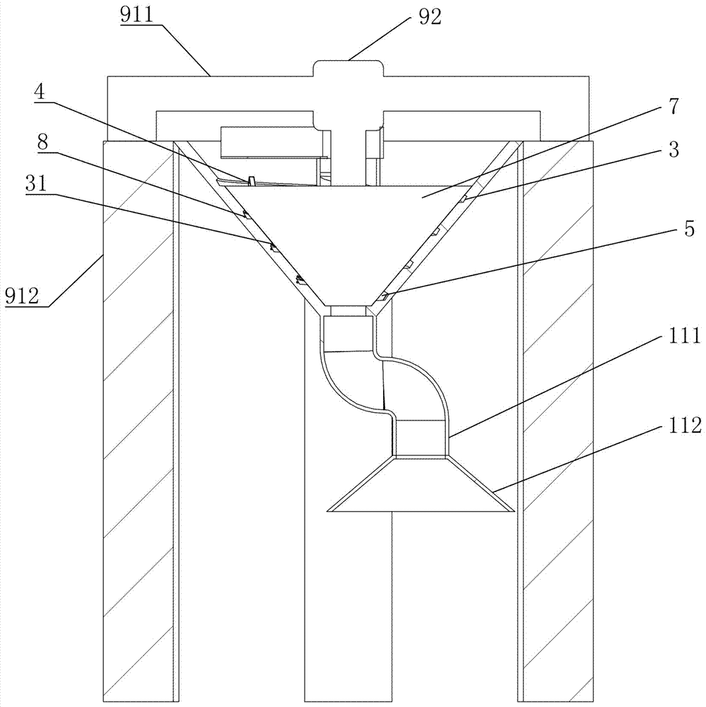
[0017] refer to Figures 1 to 5As shown, a detection and weighing device for harmful substances of marine organisms in this embodiment includes a feeding mechanism 1 for placing marine biological powder and a weighing mechanism 2 arranged below the feeding mechanism 1, and the weighing mechanism 2 It is an electronic scale, including a weighing body 22 and a tray 21 arranged on the weighing body 22 that can slide up and down. The tray 21 is arranged below the unloading mechanism 1, and the unloading mechanism 1 includes a container for storing marine biological powder. Storage funnel 11, the quantitative feeding device 12 that is arranged in the storage funnel 11, described tray 21 is arranged below the outlet of the storage funnel 11, wherein, the quantitative feeding device 12 quantitatively will the ocean in the storage funnel 11 The biological powder is transported from the discharge port to the tray 21, the weighing body 22 is coupled with the quantitative feeding device 12, and the powder weight signal on the tray 21 is transmitted to the quantitative feeding device 12, and the quantitative feeding device 12 has a weight threshold , when the powder weight of the tray 21 reaches the weight threshold, the quantitative feeding device 12 stops feeding, and the quantitative feeding device 12 includes a feeding groove 3 that is set on the inner wall of the storage funnel 11 and spirals downward toward the discharge port. The lower end of the trough 3 communicates with the discharge port, the feed trough 3 is provided with a push plate 4 and a baffle plate 5, and the inner wall of the storage funnel 11 is provided with a push plate 4 to slide back and forth in the feed trough 3. The driving assembly 6 that moves, so that the push plate 4 is close to or away from the baffle 5, so that the marine biological powder is pushed to the baffle 5 from the other end of the feeding trough 3 relative to the discharge port, the inner wall of the storage funnel 11 A funnel-shaped cover plate 7 is pasted on the top, and the outer wall of the cover plate 7 is closely attached to the inner wall of the material storage funnel 11, so as to cover the notch of the feeding chute 3, and the groove bottom and the groove wall of the feeding chute 3 and The push plate 4 and the baffle 5 form a closed space. The push plate 4 is provided with a pressure sensor 41 on the side facing the baffle 5. The pressure sensor 41 has a threshold value therein and is coupled with the drive assembly 6. When the pressure When the pressure detected by the sensor 41 exceeds the threshold, the drive assembly 6 drives the push plate 4 away from the baffle 5, and the bottom of the feeding chute 3 is close to the material storage port and is provided with a telescopic groove 111 at a position relative to the baffle 5, so The baffle plate 5 is partially embedded in the telescopic groove 111, and the bottom of the telescopic groove 111 is provided with a telescopic assembly 7 that drives the baffle plate 5 to slide back and forth in the telescopic groove 111, so that the baffle plate 5 extends into the feeding chute 3 or retracted into the telescopic groove 111, the coding line 8 is laid in the feeding groove 3, the driving assembly 6 and the telescopic assembly 7 are both coupled with the coding line 8, and the coding line 8 has a One-to-one corresponding code value, when the position of the push plate 4 is at the position of the selected code value, and the pressure sensor 41 detects that the pressure exceeds the threshold, the telescopic assembly 7 drives the baffle 5 to retract into the telescopic groove 111, and the drive assembly 6. Drive the push plate 4 to the outlet, so as to output the marine biological powder between the push plate 4 and the baffle plate 5 to the tray 21. In the process of use, it is first necessary to record the code value on the code line 8, At the same time, the weight threshold is set, which is the weight of the powder that needs to be weighed, and then the code value on the corresponding code line 8 is calculated according to the weight threshold, For example, assuming that the weight of 1 square centimeter of compacted powder is equal to 1 gram, the cross section of the feeding chute 3 in this embodiment is a square structure, with a length and width of 1 centimeter. According to the volume formula, the volume of a cuboid=bottom*height*width , therefore, the volume of the powder is the distance between the push plate 4 and the baffle plate 5 multiplied by 1 cm and then multiplied by 1 cm after the push plate 4 is pushed firmly, so the code value of the code line 8 can be set as a code of 1 cm value, it can be assumed that the coded values ​​are 0001, 0011, 0010, 0110, 0111 corresponding to 1 centimeter, 2 centimeters, 3 centimeters, 4 centimeters and 5 centimeters respectively. After the designation, it will not change, so when it is necessary to weigh 3 grams of powder, the model will be transmitted to the drive assembly 6, and the drive assembly 6 will drive the push plate 4 to continuously move the powder back and forth In the feeding trough 3, between the baffle plate 5, the baffle plate 5 in this embodiment is arranged at the end of the feeding chute 3 close to the discharge port, so as to ensure that the weight of the powder to be fed has more and larger options. When the plate 4 pushes the powder to move towards the baffle 5, the push plate 4 pushes the powder until the powder is pressed against the baffle 5 until the pressure detected by the pressure sensor 41 exceeds the threshold, so that it can effectively ensure that the push plate 4 pushes the powder every time. It is due to the state of compaction, to avoid the problem that the weight of the final output powder does not meet the requirements caused by the uneven looseness of the powder in the feeding trough 3, and at the same time record the coding line corresponding to the push plate 4 every time the push plate 4 is compacted 8 coded value, and set to when the pressure sensor 41 exceeds the threshold value, while the position of the push plate 4 reaches the required coded value, that is, when the coded value of 3 cm is 0010, it means that the required powder weight has been weighed, and then Utilize the expansion and contraction effect of the telescopic assembly 7 to retract the baffle plate 5 and push the push plate 4 to the bottom, so that the effect of transporting the weighed powder weight to the tray 21 on the weighing mechanism 2 at one time can be well realized , so compared with the manual method in the prior art, the efficiency has been greatly improved.
[0018] As an improved specific embodiment, the driving assembly 6 includes a driving motor 61 arranged on opposite sides of the push plate 4 and a gear 62 sleeved on the rotating shaft of the driving motor 61, and the groove wall of the feeding chute 3 is provided with a There is a guide rail groove 31 extending along the feeding chute 3 , gear teeth 311 are provided on the groove wall of the guide rail groove 31 , the gear 62 is meshed with the gear teeth 311 , the drive motor 61 is connected to the weighing body 22 and the coding line 8 Coupling for receiving the weight signal output by the weighing body 22, and receiving the push plate 4 position signal output by the encoding line 8, wherein the weight threshold, pressure threshold and selected encoding value are all set in the drive motor 61, through the drive motor 61 and the setting of gear 62, just can utilize the cooperating effect of gear 62 and gear tooth 311, realize the effect that driving motor 61 drives push plate 4 to move in feeding chute 3, wherein the driving motor 61 of the present embodiment has The controller, the weight threshold, the pressure threshold and the selected code value are all set in the controller, and the controller is used to realize the detection of the threshold and the control of the external drive motor 61 and the control of the telescopic assembly 7. The drive motor in this embodiment 61 chooses a micro DC motor, and the controller uses a compact DC motor controller. For example, you can choose several switching tubes and combine with a gate chip and a crystal oscillator to form a controller. The crystal oscillator is used to control the switching of the switching tube, and the switching tube is combined into a The H bridge controls the positive and negative rotation of the driving motor 61 through on-off control, and at the same time, several comparators are added before the AND gate chip, and the comparison function of the comparator is used to judge whether the threshold value is exceeded, and then the final control result is obtained by using the AND gate chip. In this way, since the switching tube, crystal oscillator, AND gate chip and comparator are relatively small in size, they can be well arranged on the body of the drive motor 61 to realize the effect of driving the push plate 4 to move.
[0019] As an improved specific embodiment, the telescopic assembly 7 includes an electromagnet 71 arranged at the bottom of the telescopic slot 111 and a magnet fixed on the side of the baffle plate 5 facing the bottom of the telescopic slot 111, the electromagnet 71 and The drive motor 61 is coupled. When the pressure value received by the drive motor 61 is greater than the pressure threshold and the code value on the code line 8 is equal to the selected code value, the electromagnet 71 is energized to generate magnetic force, and the baffle 5 is sucked into the telescopic groove 111 , using the electromagnetic field of the electromagnet 71 and the cooperation of the magnet, the effect of driving the baffle 5 to rise and fall can be well realized. At the same time, because the wall thickness of the storage funnel 11 is not large, if other methods are used, it is easy to cause failure to install Or the problem that the structural strength of the storage funnel 11 becomes low.
[0020] As an improved specific embodiment, a stirring and lifting mechanism 9 is provided above the storage funnel 11, and the stirring and lifting mechanism 9 includes a fixed bracket 91, a stirring motor 92 and a discharge nozzle 93, and the fixed bracket 91 includes Cross 911 and upright rod 912, described upright rod 912 is provided with four, is fixed on the four ends of cross 911 respectively one by one, the side of described upright rod 912 is fixedly connected with storage funnel 11, and described stirring The fuselage of motor 92 is fixed on the position of the center of cross 911, and the rotating shaft of this stirring motor 92 is arranged towards material storage funnel 11, and screw rod 921 is coaxially fixed on the rotating shaft, and the coaxial sleeve on described screw rod 921 is provided with lifting. cylinder 922, the upper end of the lifting cylinder 922 is fixedly connected with the body of the stirring motor 92, the discharge nozzle 93 is arranged on the side of the end, and the end of the lifting cylinder 922 facing away from the discharge nozzle 93 extends to the end of the feed tank 3 Compared with the other end of the discharge port, when stirring and lifting, the marine biological powder is sucked from the lower end of the lifting cylinder 922, and the powder is lifted upward by the rotation of the screw rod 921, and then flows out from the discharge nozzle 93 at the top of the lifting cylinder 922 into the In the feeding tank 3, by using the setting of the stirring and lifting mechanism 9, the powder can be stirred and then transported to the feeding tank 3, so as to avoid the agglomeration of the marine biological powder and the inability to transport the material to the feeding tank 3 well. Problem, at the same time, through the setting of the stirring motor 92 and the screw rod 921 on the rotating shaft of the stirring motor, the effect of stirring the powder can be effectively realized, and the use of the cooperation of the lifting cylinder 922 and the screw rod 921 can realize the stirring process. Therefore, in the process of using the weighing device of this embodiment, it is only necessary to pour the powder into the storage funnel and store the powder in the cover plate 7 , and then through the cooperation of the screw rod 921 and the lifting cylinder 922, the effect of stirring and lifting is realized, which is convenient for people to discharge.
[0021] As an improved specific embodiment, a material guide tube 111 extending downward is provided on the discharge port of the storage funnel 11, one end of the material guide tube 111 is fixedly connected with the discharge port, and the other end is provided with a There is a trumpet-shaped cap 112, the small opening of the cap 112 is fixedly connected to the discharge port, and the large opening is covered on the tray 21. Through the setting of the material guide tube 111, the weighed powder can be accurately transported The effect on the tray 21, and the setting of the cap 112 can avoid the problem of powder spilling out during the discharging process, further increasing the weighing efficiency of marine biological powder.
[0022] In summary, the weighing device of this embodiment, through the action of the quantitative feeding device 12 in the unloading mechanism 1, realizes the effect of open-loop control of weighing powder, and through the balance of the weighing body 22 of the weighing mechanism 2 and the tray 21 With the combined effect, a closed-loop control effect of weighing powder can be realized, making the weighing of powder more accurate and faster.
[0023] The above descriptions are only preferred implementations of the present invention, and the protection scope of the present invention is not limited to the above-mentioned embodiments, and all technical solutions under the idea of ​​the present invention belong to the protection scope of the present invention. It should be pointed out that for those skilled in the art, some improvements and modifications without departing from the principles of the present invention should also be regarded as the protection scope of the present invention.

PUM

no PUM

Description & Claims & Application Information

We can also present the details of the Description, Claims and Application information to help users get a comprehensive understanding of the technical details of the patent, such as background art, summary of invention, brief description of drawings, description of embodiments, and other original content. On the other hand, users can also determine the specific scope of protection of the technology through the list of claims; as well as understand the changes in the life cycle of the technology with the presentation of the patent timeline. Login to view more.

Similar technology patents

Automatic pipe body weighing turnover frame

Owner:昆山圣源机械有限公司

Live pig weight measuring method based on deep learning and depth camera

PendingCN113706512AImprove weighing efficiencyReduce human interventionImage enhancementImage analysisImage analysisBody weight measure
Owner:INNER MONGOLIA UNIVERSITY

Classification and recommendation of technical efficacy words

Why Eureka
Try Eureka