A microscopic imaging device with controllable position interface

A microscopic imaging and interface technology, applied in microscopy, material excitation analysis, fluorescence/phosphorescence, etc., can solve the problems of affecting imaging results and changing droplet shape

Active Publication Date: 2019-09-24
PEKING UNIV
View PDF4 Cites 0 Cited by
  • Summary
  • Abstract
  • Description
  • Claims
  • Application Information

AI Technical Summary

Problems solved by technology

In the prior art, when the water mirror of the laser confocal microscope is used to observe the interface, the movement of the laser confocal microscope during the imaging process will change the shape of the droplet, which will affect the imaging results.

Method used


Image

  • A microscopic imaging device with controllable position interface
  • A microscopic imaging device with controllable position interface

Examples


Embodiment Construction

[0015] In order to make the object, technical solution and advantages of the present invention clearer, the present invention will be further described in detail below in conjunction with specific embodiments and with reference to the accompanying drawings.

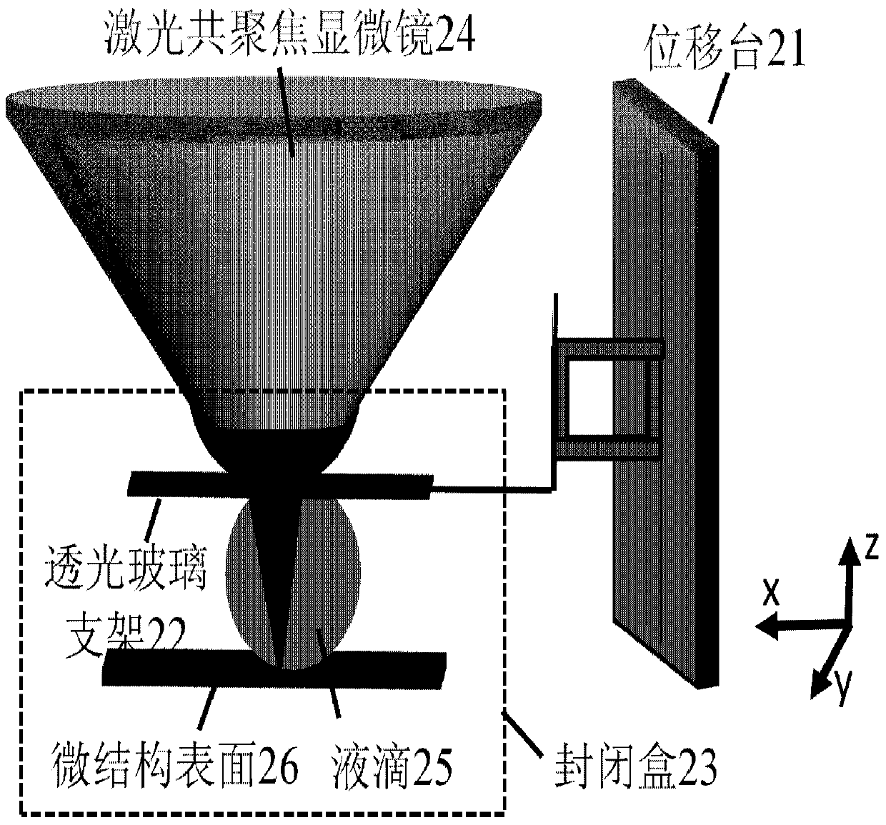
[0016] figure 1 A schematic diagram showing the structure of the microscopic imaging device of the controllable position interface proposed by the present invention. Such as figure 1 As shown, the device includes: a translation stage 21 , a light-transmitting glass support 22 , a closed box 23 , a laser confocal microscope 24 , a droplet 25 and a surface 26 with a microstructure to be measured.

[0017] Wherein, the transparent glass bracket 22 is used to carry the transparent glass, which is made of metal wire, which surrounds the periphery of the transparent glass and extends from one side of the transparent glass to form a handle;

[0018] The light-transmitting glass support 22 and the microstructure surface 26 to b...


PUM


Abstract

The invention discloses a position-controllable microscopic imaging device for an interface. The position-controllable microscopic imaging device comprises a light-transmission glass bracket, a closing box, a laser confocal microscope and a displacement platform, wherein the light-transmission glass bracket is used for supporting light-transmission glass; one side of the light-transmission glass bracket is provided with a handle; the light-transmission glass is used for suspending a to-be-measured liquid drop at the same time besides being used for supporting the position, where water needs to be used, of a lens; the closing box is used for bearing a to-be-measured microstructure and the light-transmission glass bracket; one side of the closing box is provided with a small hole through which the handle of the light-transmission glass bracket stretches out; the upper part of the closing box is provided with a circular hole through which the head of the laser confocal microscope penetrates; the displacement platform is located on one side of the closing box, and is used for adjusting the position of the light-transmission glass bracket in the closing box through the handle of the light-transmission glass bracket. Through the scheme provided by the invention, not only is the effect that the morphology of the liquid drop cannot be influenced by the movement of a hydroscope realized, but also the three-dimensional motion of the liquid drop can be realized; therefore, the required morphology of the interface can be shown.

Description

technical field [0001] The invention relates to the technical field of microscopic imaging, in particular to a microscopic imaging device capable of adjusting the position of the interface and the microscopic appearance of the interface. Background technique [0002] In order to understand the interface morphology of the droplet in contact with the microstructure surface at different positions, and to avoid the situation that the air mirror cannot observe the interface when the droplet is hydrophobic, the water mirror of the laser confocal microscope is usually used to observe and measure the microscopic interface. . In the prior art, photolithographic silicon wafers are usually used to prepare regularly arranged micron cylinder structures. The micron cylinders can be arranged on the silicon wafer in a square shape. The diameter of the cylinder is usually 30 microns and the depth is 35 microns. The distance between the center of the cylinder and the cylinder is 68.6 microns...

Claims


Application Information

Patent Timeline
Patent Type & Authority Patents(China)
IPC IPC(8): G01N21/63G01N21/64G02B21/00
Inventor 段慧玲李丹丹薛亚辉吕鹏宇
Owner PEKING UNIV
Why Eureka
Try Eureka