Micro rails for large printers

A miniature technology for printers, applied in printing, transfer materials, power transmission devices, etc., can solve the problem that the moving distance of the sliding plate and the chute cannot be changed

Active Publication Date: 2018-11-20
ZHOUSHAN JIUYIDA MACHINERY
View PDF6 Cites 0 Cited by
  • Summary
  • Abstract
  • Description
  • Claims
  • Application Information

AI Technical Summary

Problems solved by technology

[0004] The problem to be solved by the present invention is that the pile insertion in the prior art is a fixed structure, and the moving distance between the sliding plate and the chute cannot be changed

Method used


Image

  • Micro rails for large printers
  • Micro rails for large printers
  • Micro rails for large printers

Examples


Embodiment Construction

[0014] The present invention will be further described below in conjunction with the accompanying drawings and embodiments.

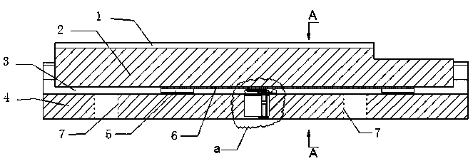
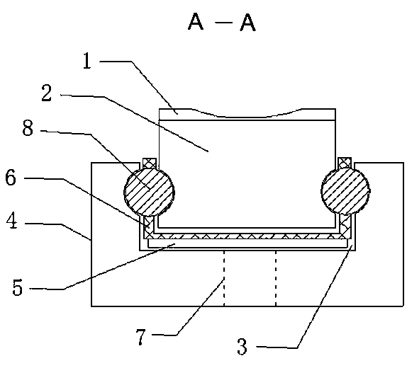
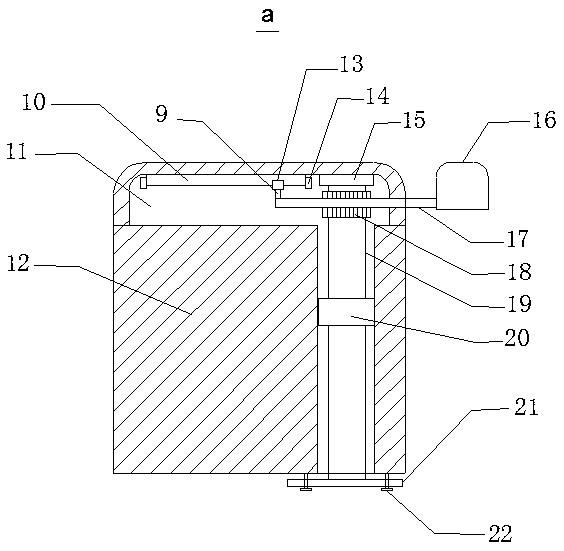
[0015] The miniature guide rail for a large printer of the present invention includes an arc plate 1, a sliding plate 2, a chute 3, a base 4, a bump 5, a plastic holder 6, a heat dissipation through hole 7, a steel ball 8, a pole 9, a slide rail 10, Groove 11, stake 12, slide block 13, limit block 14, flange bearing 15, insert block 16, rack 17, gear 18, rotating shaft 19, bearing, rotating plate 21 and screw 22, described base 4 A chute 3 is provided, and the inner bottom of the base 4 is provided with two heat-dissipating through-holes 7 , and the left and right side walls of the base 4 are respectively provided with first concave strips sunken inward, and the plastic cage 6 is arranged in the chute 3 , the left and right sides of the bottom of the plastic holder 6 are respectively equipped with protrusions 5, the protrusions 5 are located on the chut...


PUM


Abstract

The invention provides a miniature guiding rail for a large-scale printer. The miniature guiding rail comprises an arc-shaped plate, a sliding plate, a sliding groove, a base, lug bosses, a plastic holding frame, heat-dissipating through holes, a plurality of steel balls, a supporting rod, a sliding rail, a groove, an insertion pile, a sliding block, a limiting block, a flange bearing, an insertion block, a gear rack, a gear, a rotating shaft, a bearing, a rotating plate and screws, wherein the sliding groove is formed in the base; inward-concave first concave strips are correspondingly arranged on the left and right side walls of the interior of the sliding groove; the plastic holding frame is arranged in the sliding groove; the lug bosses are correspondingly mounted on the left and right sides of the bottom of the plastic holding frame, and positioned on the sliding groove; the lower bottom surfaces of the lug bosses cling to but are not fixedly connected with the upper bottom surface of the sliding groove; the steel balls are correspondingly mounted on the left and right sides of the plastic holding frame; and the sides, close to the base, of the steel balls are embedded in the first concave strips in the base. The miniature guiding rail provided by the invention has the advantage that the moving distance of the sliding plate can be changed.

Description

technical field [0001] The invention relates to a miniature guide rail for a large printer and belongs to the technical field of miniature guide rails. Background technique [0002] The inkjet head of a large printer needs to move up and down continuously. Generally, the inkjet head and the sliding plate of the linear slide rail are installed together, and the inkjet head moves up and down with the help of the sliding plate. A rolling guide, which uses steel balls to perform infinite rolling cycles between the sliding plate and the guide rail, so that the load platform can easily move linearly with high precision along the guide rail, and generally a limit plug is set between the sliding plate and the chute Stakes to limit the travel distance of the sliding panels. The stakes in the prior art are fixed structures, and the moving distance between the sliding plate and the chute cannot be changed. In order to solve the above difficulties, it is necessary to develop a micro-r...

Claims


Application Information

Patent Timeline
Patent Type & Authority Patents(China)
IPC IPC(8): B41J25/304
CPCB41J25/304
Inventor 周海军张锟孙智勇余益凤沈学良
Owner ZHOUSHAN JIUYIDA MACHINERY
Why Eureka
Try Eureka