A 3D Scanner Adaptive Calibration Method

A calibration method and scanner technology, applied in the direction of instruments, measuring devices, optical devices, etc., can solve problems such as corner overlap and camera assembly error, and achieve the effect of solving corner overlap and realizing self-adaptive calibration

Inactive Publication Date: 2019-09-27
DONGHUA UNIV
View PDF8 Cites 0 Cited by
  • Summary
  • Abstract
  • Description
  • Claims
  • Application Information

AI Technical Summary

Problems solved by technology

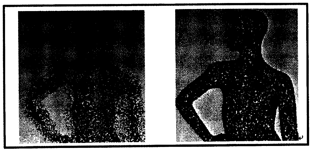
However, due to the different processing techniques of the cameras, and the objective existence of camera assembly errors (such as different degrees of distortion of the camera housing under different screw tensions) when building a 3D scanner system, it will cause corner overlap effects

Method used


Image

  • A 3D Scanner Adaptive Calibration Method
  • A 3D Scanner Adaptive Calibration Method
  • A 3D Scanner Adaptive Calibration Method

Examples


Embodiment Construction

[0031] Below in conjunction with specific embodiment, further illustrate the present invention. It should be understood that these examples are only used to illustrate the present invention and are not intended to limit the scope of the present invention. In addition, it should be understood that after reading the teachings of the present invention, those skilled in the art can make various changes or modifications to the present invention, and these equivalent forms also fall within the scope defined by the appended claims of the present application.

[0032] The invention provides a method for self-adaptive calibration of a three-dimensional scanner, comprising the following steps:

[0033] Step 1. Divide the points in the Harris corner point set into three categories. Type I points are non-boundary points and non-four corner points in the Harris corner point set, and type II points are non-four corner points in the Harris corner point set. The boundary points of the type I...


PUM


Abstract

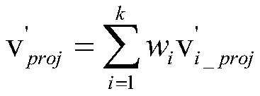
The invention provides an adaptive calibration method of a three-dimensional scanner. The method is characterized by comprising the following steps of classifying points in an Harris angular point set; establishing a Laplace coordinate for the points in each Harris angular point set; and if a three-dimensional scanning system comprises n cameras, utilizing the Harris angular point set which is acquired by a first camera as a reference, and performing adaptive adjustment on the Harris angular point sets which are acquired by other cameras. After the method provided by the invention is utilized, an angular point overlapping problem in a point marking process of the three-dimensional scanner system can be settled, and adaptive calibration to the three-dimensional scanner system is realized.

Description

technical field [0001] The invention relates to a method for self-adaptive calibration of a three-dimensional scanner system. Background technique [0002] When using multiple depth cameras to build a 3D scanner system, it is necessary to stitch together the 3D point cloud sheets collected by a single camera. The splicing principle is to use the same calibration board, on which there are 16×10 black and white squares, and the corners formed are called Harris corners. According to the imaging principle of the camera, the purpose of camera calibration is to accurately overlap several Harris corner images seen by several cameras. However, due to the different processing techniques of the cameras, and the objective existence of camera assembly errors (such as different degrees of distortion of the camera housing under different screw tensions) when building a 3D scanner system, it will cause overlapping corners. Contents of the invention [0003] The purpose of the present i...

Claims


Application Information

Patent Timeline
Patent Type & Authority Patents(China)
IPC IPC(8): G01B11/24
Inventor 钟跃崎毋戈李端
Owner DONGHUA UNIV
Why Eureka
Try Eureka