
A method of installing a sliding door

An installation method and sliding door technology, which is applied in the field of sliding doors, can solve problems such as shaking of doors, damage to sliding doors, and poor stability, and achieve the effects of improving decoration efficiency, reducing damage and pollution, and improving load-bearing capacity

Active Publication Date: 2019-05-14
NANJING GERUI GAITE DOOR IND CO LTD
View PDF8 Cites 0 Cited by
  • Summary
  • Abstract
  • Description
  • Claims
  • Application Information

AI Technical Summary

Problems solved by technology

This method has the following defects: 1. When decorating, the site is relatively messy. The sliding door is installed first, and the price sliding door will be dirty when the decoration is carried out. Some stains are difficult to clean up, resulting in the overall sliding door It is not beautiful, affects the use, and may also cause damage to the sliding door;
[0004] 2. The connecting piece extending to the outside of the hanging rail through the hanging wheel and the upper surface of the sliding door leaf are fixed by screws. This way makes the gap between the door leaf and the hanging rail larger, which affects the appearance, especially for high-end sliding doors. its effects are severe;
[0005] 3. Since there is no guide rail at the bottom, only the upper guide rail and the hanging wheel are used for limit linkage, which will easily cause shaking between the doors, poor stability, and affect the use. Therefore, the bottom of each sliding door needs a linkage limit mechanism , most of the existing linkage limit mechanisms use guide wheels to contact the ground, which has a great impact on the overall appearance

Method used


Image

  • A method of installing a sliding door
  • A method of installing a sliding door
  • A method of installing a sliding door

Examples


Embodiment Construction

[0040] The present invention will be further clarified below with reference to the drawings and specific embodiments. This embodiment is implemented on the premise of the technical solution of the present invention. It should be understood that these embodiments are only used to illustrate the present invention and not to limit the scope of the present invention.

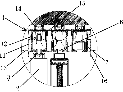
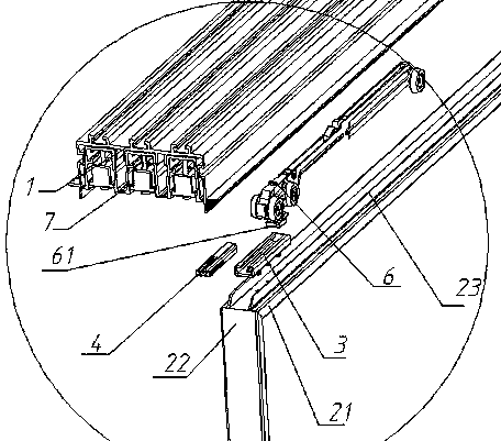
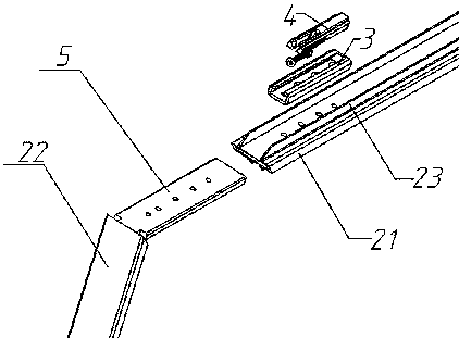
[0041] The invention discloses a method for installing a sliding door, which is based on the invention Figure 1-6 The structure of the sliding door shown is realized. The installation structure of the sliding door includes a guide rail 7, a hanging wheel 6, and a sliding door leaf structure 2, a sub-frame mechanism 1. The sub-frame mechanism 1 includes a sub-frame body, and The sub-frame body includes a top plate 15 and left and right side plates 11.

[0042] A limit plate 12 for installing the guide rail 7 is provided in the sub-frame body. The number of limit plates 12 in the sub-frame body is determined according to...


PUM


Abstract

The invention discloses a mounting method of sliding doors. The mounting method of the sliding doors includes the following steps of mounting a sub-frame on a cross beam before decorating the ceiling; mounting guide rails corresponding to a plurality of sliding doors on the sub-frame; mounting hanging wheels in the guide rails; assembling an upper frame profile, a side profile, a bottom side profile of each sliding door leaf and glasses, and fixing a hanging wheel loading groove to the upper frame profile of an upward-sliding door leaf; fixing each sliding door leaf with each hanging wheel; mounting a hanging wheel mounting block from the opening of the hanging wheel loading groove which is arranged on the upper frame profile of each sliding door leaf, inserting an expansion block in the hanging wheel loading groove to clamp the hanging wheel mounting block after the hanging wheel mounting block is put in the hanging wheel loading groove; and mounting a door bottom limit linkage mechanism on each sliding door, specifically, connecting the bottom side profiles of every two sliding doors with each other through connecting pieces after fixing each sliding door leaf and each hanging wheel well. The mounting method of the sliding doors can reduce the construction difficulty effectively, meanwhile improve the safety and stability of the sliding doors, and improve the aesthetics of the sliding doors.

Description

Technical field [0001] The present invention relates to the field of sliding doors, and in particular to an installation method for sliding doors. Background technique [0002] As a new type of door structure, sliding door has the advantages of flexible opening and small space after opening. The characteristic of hanging rail door is that there is no lower rail. For spaces that are not suitable for installing lower rails, as well as some high-end residences and places, they are all used Hanging rail door. [0003] The existing installation method of hanging rail sliding door mainly includes several steps: (1) directly fix the guide rail to the beam or reserved steel frame by means of screws, (2) install the hanging wheel in the guide rail, and lift the The wheel is directly fixed to the upper frame of the door leaf by screws. (3) After the sliding door is installed, the ceiling is suspended, and the guide rail is hidden in the gypsum board. This method has the following shortcomi...

Claims


Application Information

Patent Timeline
Patent Type & Authority Patents(China)
IPC IPC(8): E06B3/46E06B1/02E05D15/06
CPCE05D15/0647E06B1/02E06B3/4636
Inventor 任晓萍
Owner NANJING GERUI GAITE DOOR IND CO LTD
Learn More