

Multi-frame output control method and device
An output control, multi-screen technology, applied in the direction of image communication, selective content distribution, electrical components, etc., can solve the problems of cumbersome, multi-screen cannot be switched in real time, etc.
- Summary
- Abstract
- Description
- Claims
- Application Information
AI Technical Summary
Problems solved by technology
Method used
Image

Examples
no. 1 example
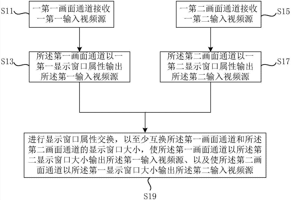
[0033] Such as figure 1 As shown, the multi-picture output control method provided in the first embodiment of the present invention includes the following steps:
[0034] S11: A first image channel receives a first input video source;
[0035] S13: The first image channel outputs the first input video source with a first display window attribute;
[0036] S15: A second image channel receives a second input video source;
[0037] S17: The second image channel outputs the second input video source with a second display window attribute;
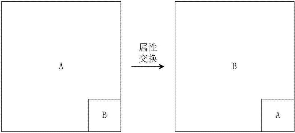
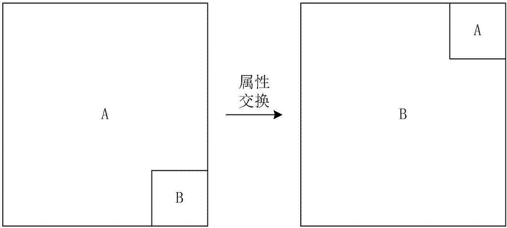
[0038] S19: Exchanging display window attributes to at least exchange the display window sizes of the first picture channel and the second picture channel, so that the first picture channel outputs the first input video with the second display window size source, and causing the second picture channel to output the second input video source in a first display window size.
[0039] In order to facilitate the understanding of the multi-screen...
no. 2 example
[0049] Such as Figure 5 As shown, a multi-picture output control device 50 provided in the second embodiment of the present invention includes: a first picture channel 51, a second picture channel 53 and a display window attribute exchange module 55, and preferably also includes a layer state attribute Interchange module 57.
[0050] Wherein, the first picture channel 51 is used to receive a first input video source and output the first input video source with a first display window attribute, wherein the first display window attribute includes a first display window size and a first Display window starting position.
[0051] The second picture channel 53 is used to receive a second input video source and output the second input video source with a second display window attribute, wherein the second display window attribute includes a second display window size and a second display window starting point.
[0052] The display window attribute exchange module 55 is configure...
no. 3 example
[0056] Such as Image 6 As shown, a method for controlling multi-picture output provided in the third embodiment of the present invention includes the following steps:
[0057] S61: Select at least one first picture channel as a first switching group;
[0058] S63: Select at least one second picture channel as the second switching group;
[0059] S65: Perform image attribute exchange between the at least one first picture channel in the first exchange group and the at least one second picture channel in the second exchange group.
[0060] In this embodiment, the first exchange group and the second exchange group typically have the same number of picture channels, and image attributes are exchanged between the two, for example, the size of the display window and the initial position of the display window in the attributes of the display window are exchanged , or even exchange the layer state attribute in the image attribute; and the specific exchange method can refer to the r...
PUM
 Abstract
Description
Claims
Application Information