Display panel

A display panel and display area technology, which is applied in the directions of instruments, calculations, electrical digital data processing, etc., can solve the problems of occupying non-display area space and unfavorable narrow frame design, etc., to achieve narrow frame design and facilitate thin design , the effect of reducing space

Active Publication Date: 2017-07-11
SHANGHAI TIANMA MICRO ELECTRONICS CO LTD
View PDF4 Cites 9 Cited by
  • Summary
  • Abstract
  • Description
  • Claims
  • Application Information

AI Technical Summary

Problems solved by technology

Due to the large number of touch signal lines, it will take up a large space in the non-display area, which is not conducive to the design of narrow borders

Method used


Image

  • Display panel
  • Display panel
  • Display panel

Examples


Embodiment Construction

[0029] The principles and features of the present application will be further described in detail below in conjunction with the drawings and embodiments. It should be understood that the specific embodiments described here are only used to explain related inventions, rather than to limit the invention. It should also be noted that, for ease of description, only parts related to the invention are shown in the drawings.

[0030] It should be noted that, in the case of no conflict, the embodiments in the present application and the features in the embodiments can be combined with each other. The present application will be described in detail below with reference to the accompanying drawings and embodiments.

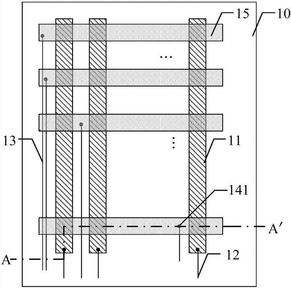
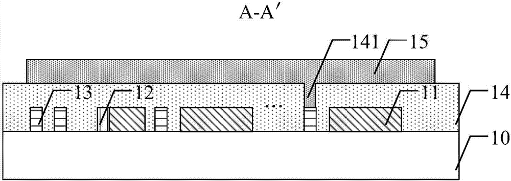
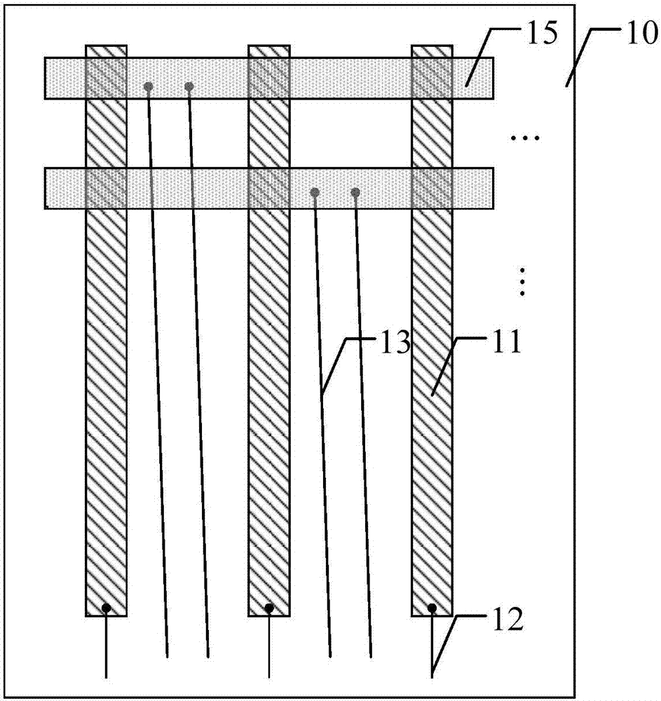
[0031] See Figure 1a , which shows a schematic structural diagram of an embodiment of the display panel provided by the present application. The display panel may include: a substrate 10; a first touch electrode 11, a first touch signal line 12 and a second touch signal ...


PUM


Abstract

The application discloses a display panel. The display panel comprises a base material; a first touch electrode, a first touch signal line and a second touch signal line which are arranged on the base material, wherein the first touch electrode is electrically connected with the first touch signal line; an insulating layer which covers the base material, the first touch electrode, the first touch signal line and the second touch signal line; a second touch electrode located on an insulating layer, wherein an extending direction of the second touch electrode is intersected with an extending direction of the first touch electrode, and each second touch electrode is electrically connected with at least one second touch signal line through a via hole, the second touch signal line is insulated from the first touch electrode and the first touch signal line, and at least one second touch signal line is formed between two first touch electrodes. At least one second touch signal line is formed between two first touch electrodes through the implementation way, the space of a non-display area occupied by the second touch signal line can be reduced, thereby benefiting the realization of the design of a narrow frame.

Description

technical field [0001] The present application relates to the field of display technology, in particular to a display panel. Background technique [0002] At present, existing touch display panels are mainly divided into mutual-capacitance display panels and self-capacitance display panels. The mutual capacitive display panel usually includes touch emitting electrodes and touch sensing electrodes. The extending direction of the touch emitting electrode intersects with the extending direction of the touch sensing electrode, and the touch position is determined by the mutual capacitance formed in the overlapped area. [0003] The touch emitting electrodes and the touch sensing electrodes generally respectively transmit touch driving signals and touch sensing signals through touch signal lines. The touch signal lines electrically connected to the touch sensing electrodes are usually routed along the non-display area of ​​the display panel. Due to the large number of touch si...

Claims


Application Information

Patent Timeline
Patent Type & Authority Applications(China)
IPC IPC(8): G06F3/041G06F3/044
CPCG06F3/041G06F3/0412G06F3/044
Inventor 李谷骏杜凌霄
Owner SHANGHAI TIANMA MICRO ELECTRONICS CO LTD
Why Eureka
Try Eureka