Light guide structure for implementing polarization collimation surface light sources

A light guide structure and collimating surface technology, applied in the field of lighting optics, can solve the problems of difficult to balance optical performance and high integration, light transmittance decrease, light energy utilization rate decrease, etc., to achieve thin design, structure The effect of complete function and easy processing technology

Active Publication Date: 2016-04-20
FUZHOU UNIV
View PDF8 Cites 8 Cited by
  • Summary
  • Abstract
  • Description
  • Claims
  • Application Information

AI Technical Summary

Problems solved by technology

However, the black ultra-fine louver material on the light control film will absorb light, which will reduce the light transmittance and greatly reduce the utilization rate of light energy, resulting in insufficient lighting brightness.
In summary, the existing lighting devices are difficult to take into account the problems of optical performance and high integration, and some lighting requirements such as liquid crystal display backlight modules also have requirements for collimation and polarization. In order to solve this problem, it is necessary Provide a surface light source structure with complete structure and function, easy process realization and low cost

Method used


Image

  • Light guide structure for implementing polarization collimation surface light sources
  • Light guide structure for implementing polarization collimation surface light sources
  • Light guide structure for implementing polarization collimation surface light sources

Examples


Embodiment Construction

[0031] The present invention will be further described below in conjunction with the accompanying drawings and specific embodiments.

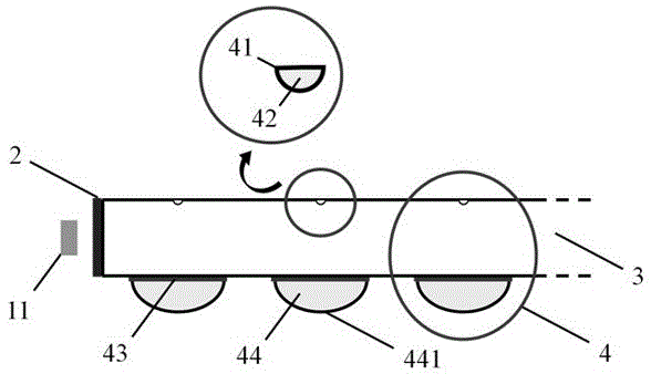
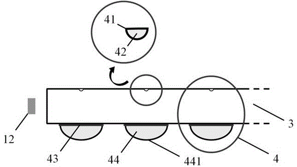
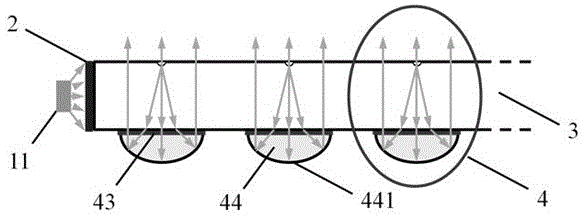
[0032] In the attached drawings, the incident light source, polarizing element, light guiding structure main body, parabolic reflective collimating microlens, quarter-wave plate, concave dimming network, and reflective polarizer are idealized models, which should not It is considered to strictly regulate its parameters and geometric dimensions. Here, the accompanying drawings of the specification are schematic diagrams of idealized embodiments of the present invention, and the illustrated embodiments of the present invention should not be considered limited to the specific shapes of the regions shown in the drawings, but include other shapes that can achieve the same function . The accessories in this embodiment, the representation in the figure is schematic, but this should not be considered as limiting the scope of the present invention.

...


PUM


Abstract

The invention discloses a light guide structure for implementing polarization collimation surface light sources. The light guide structure comprises a light guide structure body, an incident polarization light source and a micro-lens array group. Light rays emitted by the incident polarization light source are reversely transmitted into a quarter-wave plate under the effects of concave dimming screen dots arranged at a light emergent surface, are modulated twice and are collimated by parabolic reflection micro-lenses, and the high-polarization collimation surface light sources in polarization states perpendicular to original polarization states can be ultimately formed at the light emergent surface. The light guide structure has the advantages that the efficient polarization collimation surface light sources can be implemented, the light guide structure is high in integration level, particularly suitable for application with requirements on surface light sources and favorable for thinning designs of system structures and is compact, and processing techniques are easy to implement.

Description

technical field [0001] The invention relates to the field of illumination optics, is especially suitable for the application requiring polarized collimation surface light sources, and is beneficial to the highly integrated design of the system structure. In particular, it can be applied to the backlight module of liquid crystal display. Background technique [0002] In recent years, with the further expansion of lighting demand, the requirements for lighting quality and lighting system structure in various fields of society have become more and more stringent, and lighting optical devices that can achieve diversified goals have broader application prospects. Taking liquid crystal display as an example, the liquid crystal panel itself emits light passively, and a special structure needs to be designed to provide it with a polarized surface light source. The backlight module commonly used in liquid crystal display mainly includes light source, reflector, light guide plate, di...

Claims


Application Information

Patent Timeline
Patent Type & Authority Applications(China)
IPC IPC(8): G02B6/00
CPCG02B6/005G02B6/0055G02B6/0056
Inventor 陈恩果徐胜叶芸郭太良林金堂林志贤黄佳敏
Owner FUZHOU UNIV
Why Eureka
Try Eureka