Lower rivet feed mechanism for automatic button-riveting machines

The technology of a feeding mechanism and a buttoning machine is applied in the direction of sewing tools and other directions, which can solve the problems of the sticking of the push rod, the difficulty of the feeding device, and the crash of the machine.

Active Publication Date: 2017-07-14
WENZHOU ZHONGKE AUTOMATION EQUIP
View PDF9 Cites 3 Cited by
  • Summary
  • Abstract
  • Description
  • Claims
  • Application Information

AI Technical Summary

Problems solved by technology

[0002] The button sewing machine is a riveting machine for decorative buttons of clothing, shoes, hats and bags. With the development of automation, automatic button sewing machines have been produced in recent years. Due to the variety of decorative buttons, it is necessary to rivet a variety of decorative buttons on the same machine. , the feeding device has a problem
At present, the nail feeding device of the automatic button sewing machine in the market is not yet mature, which affects the promotion of the automatic button sewing machine
[0003] like Figure 4 As shown, the nail feeding mechanism generally includes a frame 1, and one side of the frame 1 is provided with a feeding track 4 for conveying the nails, a feeding seat 2 arranged on the frame, a rear section of the feeding seat 2 and used for The lower nail 5 is pushed into the push rod 3 in the mould, the feed seat 2 is provided with a push guide groove 22 corresponding to the push rod 3 and a feed groove 21 corresponding to the feed track, and the feed seat 2 is provided with a buckle Part 6, the feeding groove 21 communicates with the pushing groove 22 and the two form a certain angle, and the pushing groove is located at the angle (the intersection of the feeding groove and the pushing groove) to form a workpiece positioning groove, and the stop The fastener 6 blocks the lower nail 5 before feeding, so that the lower nail 5 is located at the position of the workpiece positioning groove. Since the chassis of the lower nail 5 is relatively thin, when the feeding track 4 moves, the adjacent lower nail 5 chassis will The overlap causes the second nail to be inclined. Since the section of the feeding track is larger than the nail itself, there is a gap between the nail and the feeding track. When the push rod 3 pushes the workpiece positioning groove to the mould, the stopper 6 Release the blocking material for the lower nail 5, when the second lower nail 5a is tilted toward the workpiece positioning groove, when the push rod 3 pushes the lower nail 5, the head of the second lower nail 5a will occasionally withstand the push rod 3 , so that the push rod is stuck and unable to move, resulting in a crash

Method used


Image

  • Lower rivet feed mechanism for automatic button-riveting machines
  • Lower rivet feed mechanism for automatic button-riveting machines
  • Lower rivet feed mechanism for automatic button-riveting machines

Examples


Embodiment Construction

[0023] The specific implementation manners of the present invention will be further described in detail below in conjunction with the accompanying drawings and embodiments. The following examples are used to illustrate the present invention, but are not intended to limit the scope of the present invention.

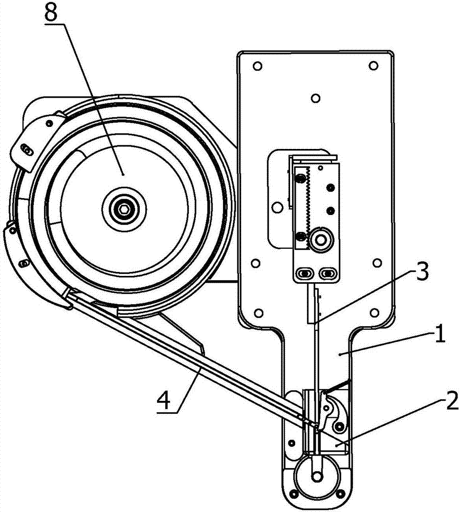
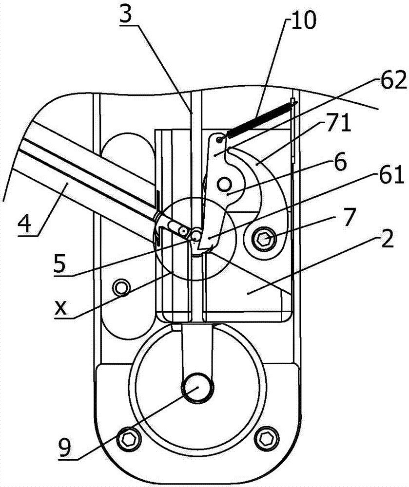
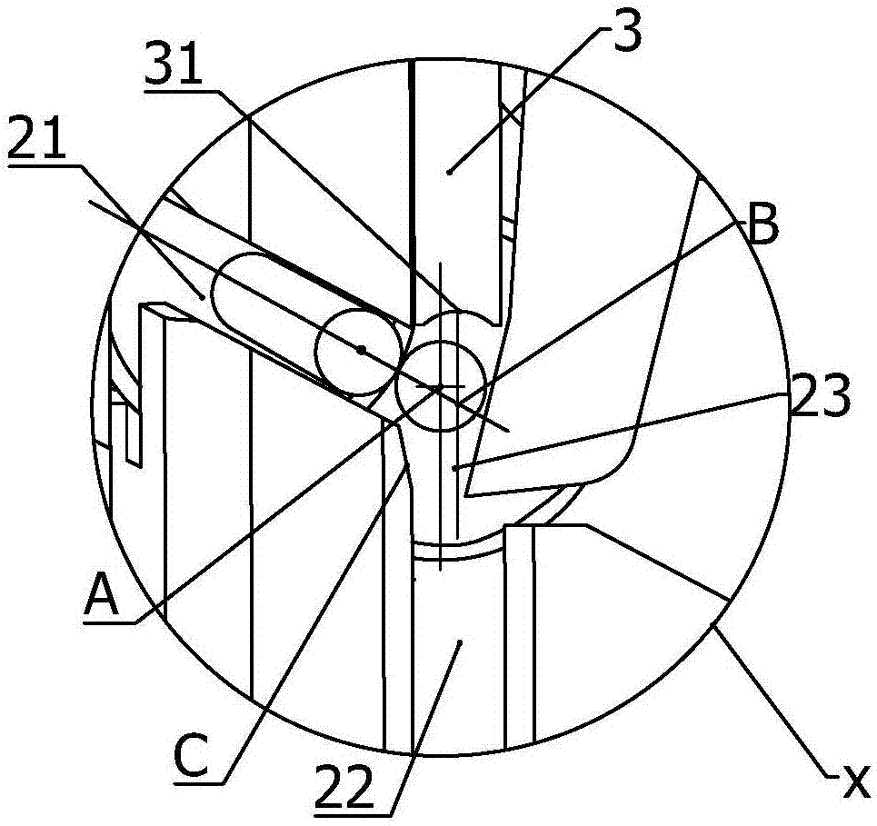
[0024] like Figure 1 to Figure 3 As shown, a feeding mechanism for nailing 5 of an automatic button sewing machine includes a frame 1, a feeding seat 2, a feeding track 4 for feeding the feeding seat 2, and a vibrating plate 8 corresponding to the feeding track, located behind the feeding seat 2 section and push the lower nail 5 sent by the feeding track 4 into the pusher rod 3 in the mold 9, and the feeding seat 2 is provided with a pusher guide groove 22 corresponding to the pusher rod 3 and a feeder corresponding to the feeding track 4 Groove 21, the position corresponding to feed trough 21 on the pushing material guide groove 22 forms workpiece positioning groove 23,...


PUM


Abstract

The invention provides a lower rivet feed mechanism for automatic button-riveting machines, which comprises a rack, a feed base, a feed track, and a push rod, wherein the feed track carries out feeding for the feed base, the push rod is located in the rear section of the feed base to push a lower rivet supplied by the feed track into a die, the feed base is provided with a push guideway corresponding to the push rod and a feed channel corresponding to the feed track, a workpiece-positioning channel is formed at a position, which corresponds to the feed channel, on the push guideway, and the feed direction of the feed channel approximately forms an angle of 90 degrees with a lower rivet discharge direction in the push guideway. The lower rivet feed mechanism for automatic button-riveting machines further comprises a blocking part which can block the lower rivet before the push rod feeds the lower rivet and can release blocking when the push rod feeds the lower rivet, the blocking part abuts against the lower rivet upon the push guideway, so that the lower rivet is eccentric from the workpiece-positioning channel and is deviated toward the rear end of the feed channel, the blocking part abuts against the lower rivet, so that the distance by which the lower rivet is deviated toward the rear end of the feed channel is adjustable, and thereby the circumstance that the push rod is jammed in the process of push due to the stacking of bottom plates of neighboring lower rivets can be prevented.

Description

technical field [0001] The invention relates to an automatic button sewing machine, in particular to a nail feeding mechanism of the automatic button sewing machine. Background technique [0002] The button sewing machine is a riveting machine for decorative buttons of clothing, shoes, hats and bags. With the development of automation, automatic button sewing machines have been produced in recent years. Due to the variety of decorative buttons, it is necessary to rivet a variety of decorative buttons on the same machine. , The feeding device has a problem. The nail feeding device of the automatic button sewing machine is not yet mature in the market, which affects the promotion of the automatic button sewing machine. [0003] like Figure 4 As shown, the nail feeding mechanism generally includes a frame 1, and one side of the frame 1 is provided with a feeding track 4 for conveying the nails, a feeding seat 2 arranged on the frame, a rear section of the feeding seat 2 and...

Claims


Application Information

Patent Timeline
Patent Type & Authority Applications(China)
IPC IPC(8): A41H37/00
CPCA41H37/00
Inventor 吴圣明
Owner WENZHOU ZHONGKE AUTOMATION EQUIP
Why Eureka
Try Eureka