Novel bridge maintenance equipment

A technology for maintaining equipment and bridges. It is applied in the directions of cleaning hollow objects, cleaning methods and utensils, chemical instruments and methods, etc. It can solve the problems of inconvenient operation, difficult cleaning, and complex structure, and achieve the effect of convenient unloading.

Inactive Publication Date: 2017-07-14
XINCHANG QIPENG AUTOMATION EQUIP
View PDF9 Cites 2 Cited by
  • Summary
  • Abstract
  • Description
  • Claims
  • Application Information

AI Technical Summary

Problems solved by technology

[0002] In the infrastructure construction of the bridge, there are many sewage pipes used to discharge sewage, and in the daily maintenance of the bridge, regular cleaning and dredging of the sewage pipes is an important measure to ensure the normal sewage discharge of the bridge. More serious sewage pipes generally adopt the operation steps of dismantling first, dredging and finally cleaning. However, due to the special structure of the sewage pipe, it is difficult to clean the inner wall of the sewage pipe. Many existing mechanical devices are used to clean the inner wall of the sewage pipe. However, these inner wall cleaning devices are complex in structure, and for different diameters of sewage pipes, different cleaning heads often need to be replaced, which is very inconvenient to operate. It is not easy to clean some stubborn stains on the inner wall of sewage pipes, and the cleaning effect is not ideal.

Method used


Image

  • Novel bridge maintenance equipment
  • Novel bridge maintenance equipment
  • Novel bridge maintenance equipment

Examples


Embodiment Construction

[0023] All features disclosed in this specification, or steps in all methods or processes disclosed, may be combined in any manner, except for mutually exclusive features and / or steps.

[0024] Any feature disclosed in this specification (including any appended claims, abstract and drawings), unless expressly stated otherwise, may be replaced by alternative features which are equivalent or serve a similar purpose. That is, unless expressly stated otherwise, each feature is one example only of a series of equivalent or similar features.

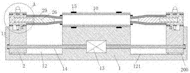
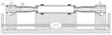
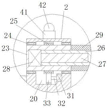
[0025] Such as Figure 1-5 As shown, a new type of bridge maintenance equipment of the present invention is used to decontaminate the inner wall of the sewage pipe 10, including a frame body 1 and decontamination devices installed on the left and right sides of the frame body 1. 10 is installed on the upper end of the frame body 1 through clips 15, and the two sides of the frame body 1 are mutually symmetrically provided with a sliding chambe...


PUM


Abstract

The invention relates to novel bridge maintenance equipment which comprises a frame body and fouling cleaning devices mounted on the left side and the right side of the frame body respectively in a symmetric manner; sliding cavities are arranged on the two sides of the frame body respectively in a symmetric manner; each of the fouling cleaning devices comprises a sliding frame mounted in the corresponding sliding cavity in a sliding manner and a rotating frame rotatably mounted at the upper end of the corresponding sliding frame through a rotating shaft; a sliding part is arranged at the bottom of each of the sliding frames; each of the sliding parts comprises a sliding wheel and a sliding rail; a mounting groove is formed in each of the sliding frames; a first driving machine is fixedly mounted on the side wall in each of the mounting grooves; a toothed wheel is fixedly mounted on the force transmission shaft of each of the first driving machines; a toothed rack connected with each of the toothed wheels in a matched manner is fixedly mounted on the outer circle of the corresponding rotating frame; a sliding groove, of which the opening directly faces a sewage pipe, is formed in each of the rotating frames; an ejector rod extending toward the sewage pipe is mounted in each of the sliding grooves in a sliding manner; a spiral hole, of which the opening is away from the sewage pipe, is formed in each of the ejector rods; a first spiral shaft is mounted in each of the spiral holes in a screw thread fit manner; each of the spiral shafts is connected with a second driving machine fixedly mounted the corresponding rotating frame.

Description

technical field [0001] The invention relates to the technical field of bridge facilities, in particular to a novel bridge maintenance equipment. Background technique [0002] In the infrastructure construction of the bridge, there are many sewage pipes used to discharge sewage, and in the daily maintenance of the bridge, regular cleaning and dredging of the sewage pipes is an important measure to ensure the normal sewage discharge of the bridge. More serious sewage pipes generally adopt the operation steps of dismantling first, dredging and finally cleaning. However, due to the special structure of the sewage pipe, it is difficult to clean the inner wall of the sewage pipe. Many existing mechanical devices are used to clean the inner wall of the sewage pipe. However, these inner wall cleaning devices are complex in structure, and for sewage pipes of different diameters, different cleaning heads often need to be replaced, which is very inconvenient to operate. It is not easy ...

Claims


Application Information

Patent Timeline
Patent Type & Authority Applications(China)
IPC IPC(8): B08B9/047B08B13/00
CPCB08B9/047B08B13/00B08B2209/04
Inventor 范苏
Owner XINCHANG QIPENG AUTOMATION EQUIP
Why Eureka
Try Eureka