Rotary lifting type mechanical hand

A manipulator and lift-type technology, applied in the field of manipulators, can solve the problem of inability to realize the rotation of clamping parts, and achieve the effects of compact structure, convenient use and simple structure

Pending Publication Date: 2017-07-14
SUZHOU UNIV OF SCI & TECH
View PDF7 Cites 20 Cited by
  • Summary
  • Abstract
  • Description
  • Claims
  • Application Information

AI Technical Summary

Problems solved by technology

[0003] The technical problem to be solved by the present invention is: in order to solve the problem in the prior art that the manipulator can only realize the lifting of the clamping parts on it, but cannot realize the rotation of the clamping parts, a rotary lifting manipulator is now provided

Method used


Image

  • Rotary lifting type mechanical hand
  • Rotary lifting type mechanical hand

Examples


Embodiment 1

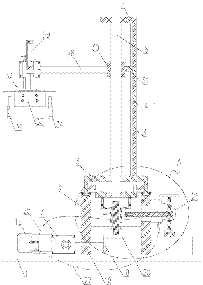
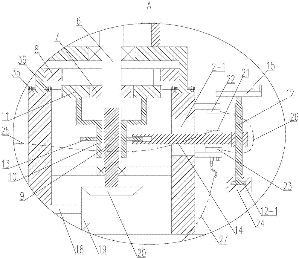
[0021] Such as figure 1 and 2 As shown, a rotary lifting manipulator includes a base 1 and a box body 2 arranged on the base 1. The upper end surface of the box body 2 is provided with a platform 3 for rotation, and a swivel ring 35 is arranged at the lower end of the platform 3. The surface is provided with an annular groove, and the swivel ring 35 is rotated and arranged in the annular groove. A pressure ring 36 is arranged above the swivel ring 35. The pressure ring 36 is fixedly connected with the box body 2 by screws, so as to realize the axial direction of the platform 3 on the box body 2. Positioning, the upper surface of the platform 3 is provided with a support 4, the top of the support 4 is provided with a top plate 5, the top plate 5 is rotated and provided with a lifting screw 6, the lifting screw 6 passes through the platform 3, and the lower end of the lifting screw 6 is fixed with an outer The gear 7, the lower surface of the platform 3 has an inner cavity, the...


PUM


Abstract

The invention relates to the technical field of mechanical hands, in particular to a rotary lifting type mechanical hand. The rotary lifting type mechanical hand comprises a base and a box body arranged on the base. A platform is rotationally arranged on the upper end face of the box body. A support is arranged on the upper surface of the platform. A top plate is arranged at the top end of the support. A lifting lead screw is rotationally arranged on the top plate. An outer gear is fixed to the lower end of the lifting lead screw. The lower surface of the platform is provided with an inner cavity. An inner gear coaxial with the outer gear is fixed to the inner ring wall of the inner cavity. When a reversing mechanism pushes a transmission gear to be engaged with the outer gear, a power device drives the lifting lead screw through the transmission gear to rotate, and therefore lifting of a clamping mechanism is achieved. When the reversing mechanism pushes the transmission gear to be engaged with the inner gear, the power device drives the whole platform through the transmission gear to rotate, accordingly, rotation of the clamping mechanism is achieved, and then workpieces clamped by the clamping mechanism can be transferred to multiple positions.

Description

technical field [0001] The invention relates to the technical field of manipulators, in particular to a rotary lifting manipulator. Background technique [0002] In the field of machinery manufacturing, in order to improve production efficiency, many enterprises generally conduct independent research and development or use mechanical automation equipment for production operations, which not only improves production efficiency, but also improves the utilization rate of materials. Existing manipulators can only achieve The lifting of the clamping part on it cannot realize the rotation of the clamping part, and then makes the manipulator have certain limitations in use. Contents of the invention [0003] The technical problem to be solved by the present invention is: in order to solve the problem in the prior art that the manipulator can only realize the lifting of the clamping parts on it, but cannot realize the rotation of the clamping parts, a rotary lifting manipulator is...

Claims


Application Information

Patent Timeline
Patent Type & Authority Applications(China)
IPC IPC(8): B25J9/10
CPCB25J9/102B25J9/109
Inventor 钱蜜陈碧榭仇鑫凯张子晔陆文浩刘子毅马江南
Owner SUZHOU UNIV OF SCI & TECH
Why Eureka
Try Eureka