Housing element with integrated heat exchanger

A technology of heat exchange elements and heat exchangers, applied in the direction of indirect heat exchangers, heat exchanger types, engine components, etc., can solve problems such as undesired economic or design reasons, shortened oil life, etc.

Inactive Publication Date: 2017-07-14
MAN NUTZFAHRZEUGE AG
View PDF6 Cites 1 Cited by
  • Summary
  • Abstract
  • Description
  • Claims
  • Application Information

AI Technical Summary

Problems solved by technology

As a result, the life of the oil is shortened
Second standard coolers or larger

Method used


Image

  • Housing element with integrated heat exchanger
  • Housing element with integrated heat exchanger
  • Housing element with integrated heat exchanger

Examples


Embodiment Construction

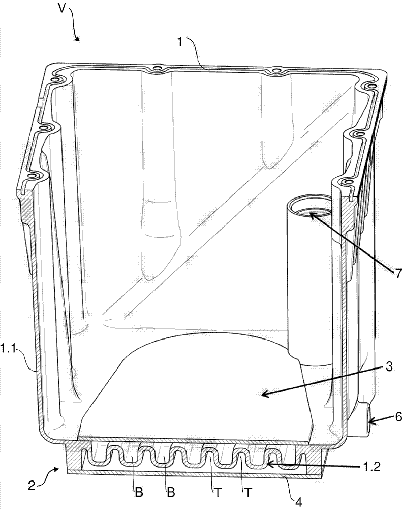
[0043] figure 1 A perspective cross-sectional view of device V (ie oil sump) for an engine (not shown), piston machine (not shown) and / or transmission arrangement (not shown) is shown.

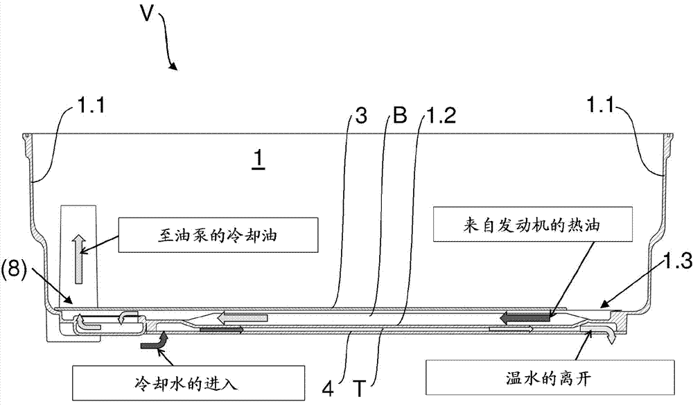
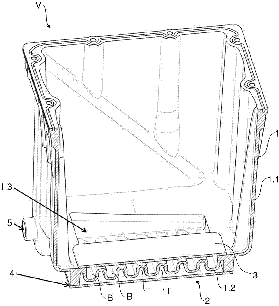
[0044] The oil sump comprises a housing element 1 for forming a side wall structure 1.1 and for containing an operating fluid, in particular oil, and a heat exchanger 2 . The heat exchanger 2 can be supplied with a temperature control fluid, eg water, and comprises a heat exchange element 1.2, by means of which heat exchange between oil and water can be achieved.

[0045] The heat exchange element 1.2 comprises a plurality of throughflow conduits B, through which oil flows during operation, and a plurality of throughflow conduits T, through which water flows during operation. Oil may be drawn in by the engine or the oil pump, for example during operation.

[0046] The heat exchange element 1.2 forms a (bottom) part of the housing element 1, with the result that the heat exchange element 1.2 ...


PUM


Abstract

A device (V) is provided, in particular an oil sump, for an engine and/or a transmission arrangement. The device (V) includes a housing element (1) for the formation of a side wall structure (1.1) and for holding an operating fluid and a heat exchanger (2) for heat exchange with the operating fluid, the heat exchanger configured to be supplied with temperature control fluid and having a heat exchange element (1.2). The heat exchange element (1.2) forms at least one through-flow duct (B) for the through flow of the operating fluid and at least one through-flow duct (T) for the through flow of the temperature control fluid.

Description

technical field [0001] The invention relates to a housing element for operating fluids, in particular oil, with an integrated heat exchanger. Background technique [0002] Especially in the case of modern engines, the oil (engine / lubricating oil) is subjected to a somewhat high pressure from the extremely high temperatures which are imposed especially on "equipment-driven engines" running continuously at maximum power. For economic reasons, the oil is generally cooled by means of standard coolers. To the extent that they are implemented in conventional sizes, standard coolers are limited in cooling capacity. That is, the oil temperature can be reduced to only a limited extent. As a result, the life of the oil is shortened. Secondary standard coolers or larger capacity coolers are generally not desirable for economical or design reasons. DE 3142327 A1 already discloses an oil sump for a combustion engine with an inner shell and an outer shell, between which the coolant fo...

Claims


Application Information

Patent Timeline
IPC IPC(8): F01M11/00F01M5/00
CPCF01M5/002F01M11/0004F01M2011/0025F01M13/04F01M2013/0422F01M2013/0438F28D9/0025F28D2021/0089F01M11/00F02F7/00F01M5/00F01P11/08
Inventor D.施利B.巴谢拉迪亚斯-布兰科M.蒂林斯基
Owner MAN NUTZFAHRZEUGE AG
Why Eureka
Try Eureka