
Easy Dispensing Syringes

A syringe and drug dispensing technology, applied in the field of syringes, can solve the problems of post-processing, cumbersome preparation, laborious suction of liquid medicine, and affecting the efficiency of diagnosis and treatment, and achieve the effects of novel structure, reduced drug waste, and high promotion value

Active Publication Date: 2019-11-22
南阳市久康医疗器械有限公司
View PDF7 Cites 0 Cited by
  • Summary
  • Abstract
  • Description
  • Claims
  • Application Information

AI Technical Summary

Problems solved by technology

[0002] In the medical field, it is often necessary to mix and prepare a variety of drugs before injecting them into the human body to treat patients; the traditional method is to inject a variety of liquid medicines into a spare container, and to make the drugs as soon as possible by continuously pumping the liquid medicine. Fusion; in order to ensure the cleanliness of the liquid medicine, the spare container often adopts an airtight structure. Therefore, it is extremely laborious to use a syringe to suck the liquid medicine. During this process, the bottle needs to be shaken continuously to speed up the mixing of the liquid medicine; After the mixing is completed, the drug is sucked out with a needle tube. Since there is always a drug remaining in the spare container, this process will cause a waste of the drug; it can be seen that the dispensing process is extremely time-consuming and seriously affects the efficiency of diagnosis and treatment; In addition, After each diagnosis and treatment, the spare container needs to be cleaned and disinfected, and the post-processing and preparation work is more cumbersome. Therefore, the traditional dispensing injection has great inconvenience

Method used


Image

  • Easy Dispensing Syringes
  • Easy Dispensing Syringes
  • Easy Dispensing Syringes

Examples


Embodiment

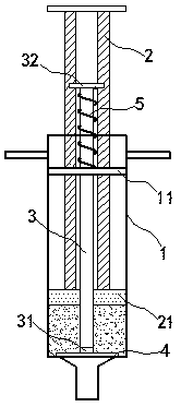
[0016] exist Figure 1 to Figure 3 In the shown embodiment, the easy-to-dispensing syringe includes a syringe 1 and a push rod 2, the end of the push rod 2 is provided with a piston plate 21, and the piston plate 21 can reciprocate and slide airtightly along the inner wall of the syringe 1; In the embodiment, the push rod 2 includes a set of parallel and rotationally symmetrical connecting rods;

[0017] A limiting plate 11 is fixedly arranged on the inner wall of the syringe 1, the push rod 2 passes through the limiting plate 11, and can reciprocate and twitch relative to the limiting plate 11;

[0018] A stirring rod 3 is also arranged in the syringe 1, and the stirring rod 3 is parallel to the push rod 2; the stirring rod 3 is arranged between the connecting rods;

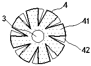
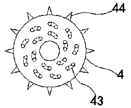
[0019] One end of the stirring rod 3 passing through the piston plate 21 is provided with a stirring piece 4, the stirring piece 4 and the stirring rod 3 are connected by a bearing 31, the stirring piece 4 can ...


PUM


Abstract

The invention relates to a syringe easy in medicine blending and a working method of the syringe. The syringe comprises a cylinder and a push rod, wherein a piston plate is arranged at an end part ofthe push rod; the piston plate is in airtight reciprocation sliding along the inner wall of the cylinder; a limiting plate is fixedly arranged on the inner wall of the cylinder; the push rod penetrates through the limiting plate and can be pulled in a reciprocation manner relative to the limiting plate; the cylinder is further internally provided with a stirring rod; the stirring rod is parallel to the push rod; a stirring blade is arranged at one end penetrating through the piston plate, of the stirring rod; a shift piece is arranged at the other end penetrating through the limiting plate, ofthe stirring rod; a spring is connected between the shift piece and the limiting plate; the stirring rod and the piston plate are kept in airtight connection; and the stirring rod can be pulled in areciprocation manner relative to the push rod. The syringe is novel and unique in structure, medicine blending procedures can be effectively simplified, the medicine blending and injection efficiencycan be greatly improved, the working pressure of medical operators can be alleviated, and meanwhile, medicine waste, medicine residues and pollution can be effectively prevented.

Description

technical field [0001] The invention relates to a medical product, especially a syringe. Background technique [0002] In the medical field, it is often necessary to mix and prepare a variety of drugs before injecting them into the human body to treat patients; the traditional method is to inject a variety of liquid medicines into a spare container, and to make the drugs as soon as possible by continuously pumping the liquid medicine. Fusion; in order to ensure the cleanliness of the liquid medicine, the spare container often adopts an airtight structure. Therefore, it is extremely laborious to use a syringe to suck the liquid medicine. During this process, the bottle needs to be shaken continuously to speed up the mixing of the liquid medicine; After the mixing is completed, the drug is sucked out with a needle tube. Since there is always a drug remaining in the spare container, this process will cause a waste of the drug; it can be seen that the dispensing process is extre...

Claims


Application Information

Patent Timeline
Patent Type & Authority Patents(China)
IPC IPC(8): A61J1/20A61M5/178A61M5/31
CPCA61J1/2003A61M5/178A61M5/31A61M5/31596
Inventor 李爱华马人欢
Owner 南阳市久康医疗器械有限公司
Learn More