Stirring roller

A technology of material shifting roller and roller body, which is applied in the field of thermal energy feeding system to achieve the effect of continuous and uniform feeding

Inactive Publication Date: 2017-07-18
常州联合锅炉容器有限公司
View PDF5 Cites 0 Cited by
  • Summary
  • Abstract
  • Description
  • Claims
  • Application Information

AI Technical Summary

Problems solved by technology

The roller bodies in the prior art lack this function

Method used


Image

  • Stirring roller
  • Stirring roller

Examples


Embodiment Construction

[0011] In order to make the content of the present invention more clearly understood, the present invention will be further described in detail below based on specific embodiments and in conjunction with the accompanying drawings.

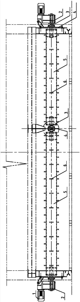
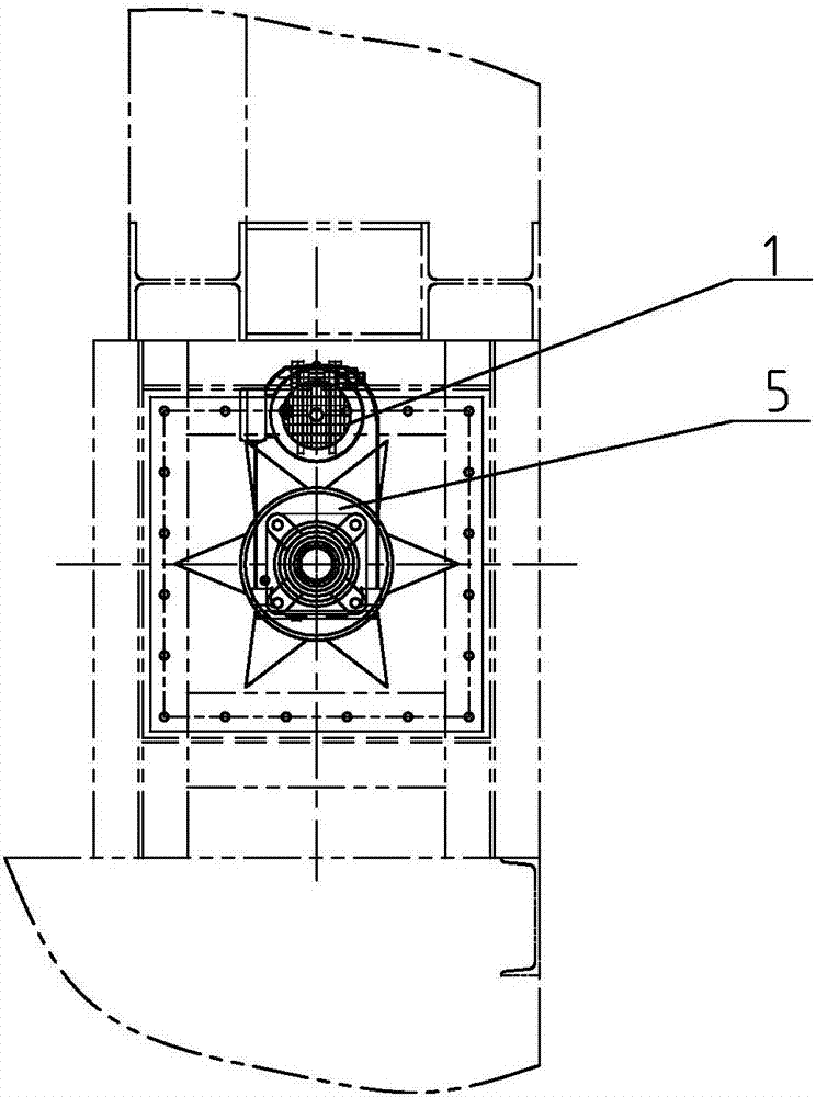
[0012] Such as figure 1 , 2 As shown, a material shifting roller includes a roller body 5 with shafts 2 at both ends, the shafts 2 at both ends of the roller body 5 are supported on a fixed support 4 through bearings 3, and the shaft 2 at the outer end of the roller body 5 extends out of the fixed support The seat 4 is connected with the speed reducer 1 through a transmission mechanism, and a plectrum 6 is installed on the outer circle of the roller body 5, and the plectrum 6 is a raised nail.

[0013] Such as figure 1 , 2 As shown, the picks 6 are evenly arranged on the outer circle of the roller body 5 .

[0014] The working principle of the present invention is as follows:

[0015] In the present invention, a paddle 6 is arranged on the out...


PUM


Abstract

The invention discloses a stirring roller. The stirring roller comprises a roller body (5) of which the two ends are provided with shafts (2); the shafts (2) at the two ends of the roller body (5) are supported on fixing supports (4) through bearings (3); the portions, at the outer ends of the roller body (5), of the shafts (2) are connected with reducers (1) trough transmission mechanisms after extending out of the fixing supports (4); and stirring sheets (6) are installed on the excircle of the roller body (5). Through the stirring roller, block materials can be dispersed and distributed uniformly so that continuous and even feeding can be ensured.

Description

technical field [0001] The invention relates to a material shifting roller, which is used in the field of thermal energy feeding systems. Background technique [0002] At present, in the thermal energy feeding system, the opening height of the live-bottom silo is about 1m, and the waste in the silo contains bark, wood chips, fibers, waste boards, etc., which will be entangled and bonded in the process of pushing the push plate. Together, they form large lumps, and in severe cases, they will be blocked at the discharge port and hinder the feeding of the boiler. Dispersing and evenly distributing these blocks of material to ensure continuous and uniform feeding is an urgent problem to be solved at present. The roller bodies of the prior art lack this function. Contents of the invention [0003] The technical problem to be solved by the present invention is to provide a material shifting roller capable of breaking up and evenly distributing the block materials in the silo. ...

Claims


Application Information

Patent Timeline
IPC IPC(8): B65D88/68
CPCB65D88/68
Inventor 韩舟绪万平
Owner 常州联合锅炉容器有限公司
Why Eureka
Try Eureka