Unit oil return control method, device and system
A technology of oil return control and unit, applied in the field of control, can solve problems such as indoor temperature reduction
- Summary
- Abstract
- Description
- Claims
- Application Information
AI Technical Summary
Problems solved by technology
Method used
Image

Examples
Embodiment 1
[0034] The embodiment of the present invention provides an embodiment of the oil return control system of the unit.
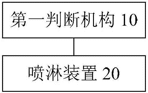
[0035] figure 1 It is a schematic diagram of an oil return control system of a unit according to an embodiment of the present invention. like figure 1 As shown, the system includes: a first judging mechanism 10 and a spraying device 20 .
[0036] The first judging mechanism 10 is used to judge whether the unit enters the oil return control.
[0037] Before judging whether the unit enters the oil return control, obtain the heated liquid in order to absorb heat for the heat exchanger through the liquid sprayed on the heat exchanger, thereby reducing the heat absorption to the indoor side. In order to avoid the phenomenon of dirty blockage and fouling of the heat exchanger caused by long-term use of liquid, the liquid is filtered.
[0038]Optionally, the unit includes a water storage tank, and the water storage tank is used for storing liquid, and the liquid m...
Embodiment 2
[0068] The embodiment of the invention also provides an oil return control method of the unit. It should be noted that the oil return control method of the unit in this embodiment can be used to implement the oil return control system of the unit in the embodiment of the present invention.
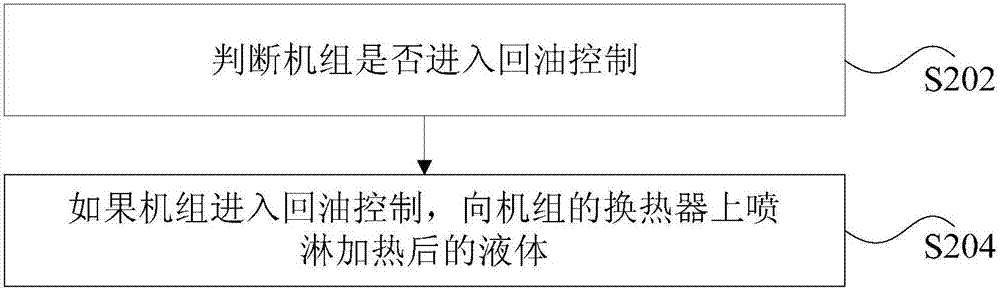
[0069] figure 2 It is a flowchart of a method for controlling oil return of a unit according to an embodiment of the present invention. like figure 2 As shown, the method includes the following steps:
[0070] Step S202, judging whether the unit enters oil return control.
[0071] In the technical solution provided in the above step S202 of the present application, it is judged whether the unit enters the oil return control.
[0072] Before judging whether the unit enters the oil return control, obtain the heated liquid in order to absorb heat for the heat exchanger through the liquid sprayed on the heat exchanger. In order to avoid the phenomenon of dirty blockage and fouling of th...
Embodiment 3
[0109] The technical solutions of the present invention will be described below in conjunction with preferred embodiments.
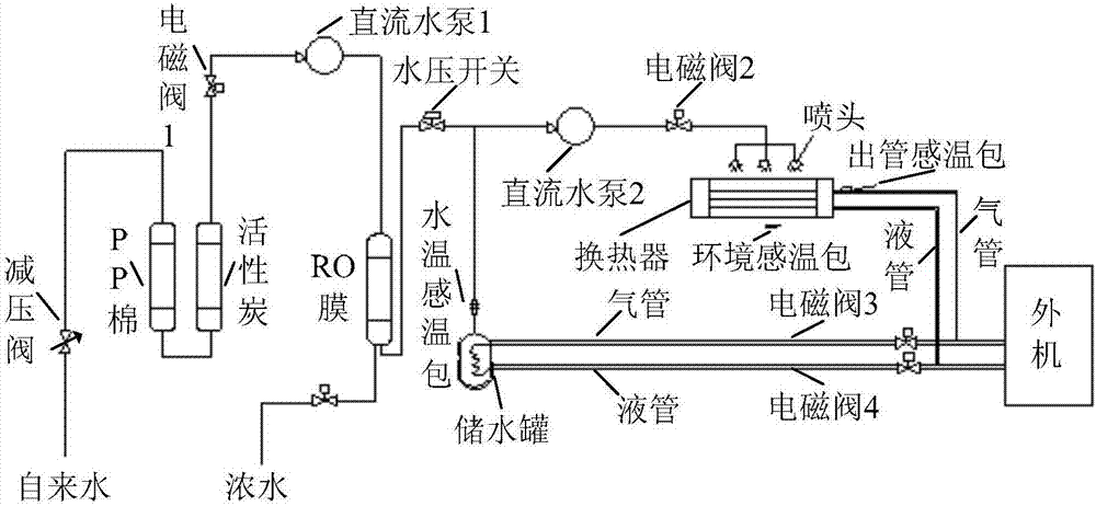
[0110] This embodiment needs to automatically process the tap water before the early oil return control, and eliminate the sodium and magnesium plasma in the tap water to obtain clean water by automatically purifying the tap water. 3. Solenoid valve 4 and other components are controlled to produce clean hot water. After the air conditioner has been running for a period of time, due to the long-term low-frequency operation of the external unit, it enters the reversing oil return control. At this time, the treated clean hot water passes through the pipeline Spray directly onto the heat exchanger, and the heat required for the evaporation of the inner heat exchanger during the oil return process is obtained from clean hot water. At the same time, it reduces the heat absorption from the indoor air, which leads to a decrease in the inner temperature, so as to...
PUM
 Abstract
Description
Claims
Application Information
 - R&D Engineer
- R&D Manager
- IP Professional
- Industry Leading Data Capabilities
- Powerful AI technology
- Patent DNA Extraction
Browse by: Latest US Patents, China's latest patents, Technical Efficacy Thesaurus, Application Domain, Technology Topic.
© 2024 PatSnap. All rights reserved.Legal|Privacy policy|Modern Slavery Act Transparency Statement|Sitemap