Ash removal structure of dust collector and dust collector

A vacuum cleaner and dust cleaning technology, which is applied in the direction of vacuum cleaners, suction filters, cleaning equipment, etc., can solve problems such as inconvenient cleaning methods, easy slipping of the dust collection bucket, and unstable connection structure

Active Publication Date: 2017-07-21
XIAOGOU ELECTRIC INTERNET TECH BEIJING CO LTD
View PDF6 Cites 0 Cited by
  • Summary
  • Abstract
  • Description
  • Claims
  • Application Information

AI Technical Summary

Problems solved by technology

[0005] The purpose of the present invention is to provide a dust removal structure of a vacuum cleaner to solve the problems existing in the prior art. When cleaning, hold the handle of the dust bucket and open the bottom cover to clean it. The technical problem is that the cleaning method is inconvenient.

Method used


Image

  • Ash removal structure of dust collector and dust collector
  • Ash removal structure of dust collector and dust collector
  • Ash removal structure of dust collector and dust collector

Examples


Embodiment 1

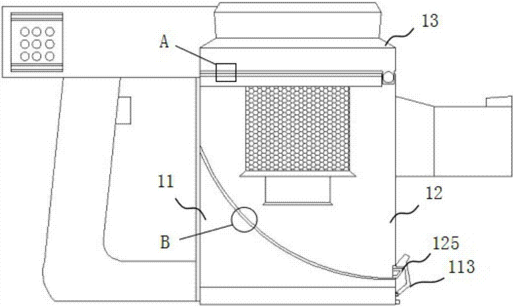
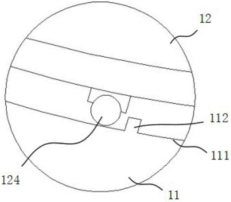
[0053] Such as figure 1 -4, in one embodiment of the present invention, the upper end surface of the base 11 forms a first arc-shaped surface, a third connecting groove 111 is formed on the first arc-shaped surface, and the dust collecting part 12 The lower end surface of the lower end surface forms a second arc surface, forms a third connection protrusion 123 on the second arc surface, and connects a pulley 124 on the third connection protrusion 123, so that the pulley 124 is on the The third connection groove 111 is slidingly connected, and a limit block 112 is also provided in the third connection groove 111, so that when the pulley 124 slides in the third connection groove 111, the limit block 112 The sliding position of the pulley 124 is limited; the upper end surface of the dust collecting part 12 forms a first connecting groove 121, and the lower end surface of the filtering part 13 forms a first connecting protrusion 131, and the first connecting protrusion 131 is con...

Embodiment 2

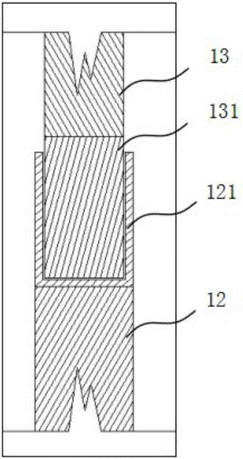
[0058] Such as Figure 5 -6, in one embodiment of the present invention, the difference from Embodiment 1 is that in order to connect the first connecting protrusion 131 on the filter part 13 with the first connecting groove on the dust collecting part 12 121, the second connecting groove 132 is set on the first connecting protrusion 131, and the second connecting protrusion 122 is set in the first connecting groove 121, so that the upper part of the dust collecting part 12 The end surface can be firmly combined with the lower end surface of the filter part 13 to prevent dust from leaking. Other structures and usage modes of this embodiment are the same as those of Embodiment 1.

[0059] The dust cleaning structure of the vacuum cleaner provided by the present invention, the bottom end surface of the dust collecting part and the top end surface of the base are both connected by an arc structure with the same radian, so that the bottom end surface of the dust collecting part i...


PUM


Abstract

The invention provides an ash removal structure of a dust collector and relates to the technical field of dust collector fittings. The ash removal structure of the dust collector comprises a base seat, a dust collection part and a filtering part; a first arc face is arranged on the base seat, a second arc face is arranged on one end of the dust collection part, and the second arc face of the dust collection part is collected with the first arc face of the base seat in a matched mode; the filtering part is connected to the other end of the dust collection part, and the filtering part is connected with the dust collection part through a connecting shaft so that a handle of the dust collection part can drive the dust collection part to rotate around the center of the connecting shaft. In the prior art, a dust collection barrel of the dust collector has a simple structure and a single function, and technical problems of the secondary pollution can be easily caused in the using process. According to the ash removal structure of the dust collector, the filtering part is connected to the upper end of the dust collection part by adopting the connecting shaft, the base seat is connected to the lower end of the dust collection part by adopting the arc face, the lower end of the dust collection part can be driven to slide along the base seat by gripping the handle, accordingly, the dust in the dust collection barrel is cleaned out, the cleaning mode is easy, and the usage is convenient.

Description

technical field [0001] The invention relates to the technical field of vacuum cleaner accessories, in particular to a dust cleaning structure of a vacuum cleaner and the vacuum cleaner. Background technique [0002] Vacuum cleaners are mainly used to absorb indoor dust. According to the structure of vacuum cleaners, they can be divided into vertical vacuum cleaners, horizontal vacuum cleaners and portable vacuum cleaners. Vertical vacuum cleaners are mainly suitable for large-area carpet cleaning. The vacuum cleaner is light and flexible to use and has good cleaning effect. The working principle of the vacuum cleaner is that the motor rotates at a high speed, and the air is sucked in from the suction port, so that a certain vacuum is generated in the dust box. In the dust filter bag, the filtered air enters the motor through a layer of filter. This layer of filter is a protective barrier to prevent the broken dust bag from entering the motor. After entering the motor, the a...

Claims


Application Information

Patent Timeline
IPC IPC(8): A47L9/10
CPCA47L9/10A47L9/1683
Inventor 檀冲
Owner XIAOGOU ELECTRIC INTERNET TECH BEIJING CO LTD
Why Eureka
Try Eureka