Grain sampler pipe head

A technique for sampling and tube, which is applied in the field of the tube head of the food sampler, can solve the problems of inconvenient use of the tube head of the sampler, and achieves the effects of speeding up the fluidity, reasonable structure and not easy to block.

Pending Publication Date: 2021-05-04
中央储备粮日照仓储有限公司
View PDF0 Cites 0 Cited by
  • Summary
  • Abstract
  • Description
  • Claims
  • Application Information

AI Technical Summary

Problems solved by technology

[0004] The purpose of the present invention is to solve the technical problem of inconvenient use of the tube head of the prior art, and provide a tube head of the grain sampler to solve the deficiencies of the prior art

Method used


Image

  • Grain sampler pipe head
  • Grain sampler pipe head

Examples


Embodiment 1

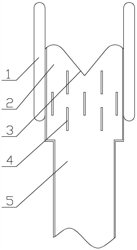
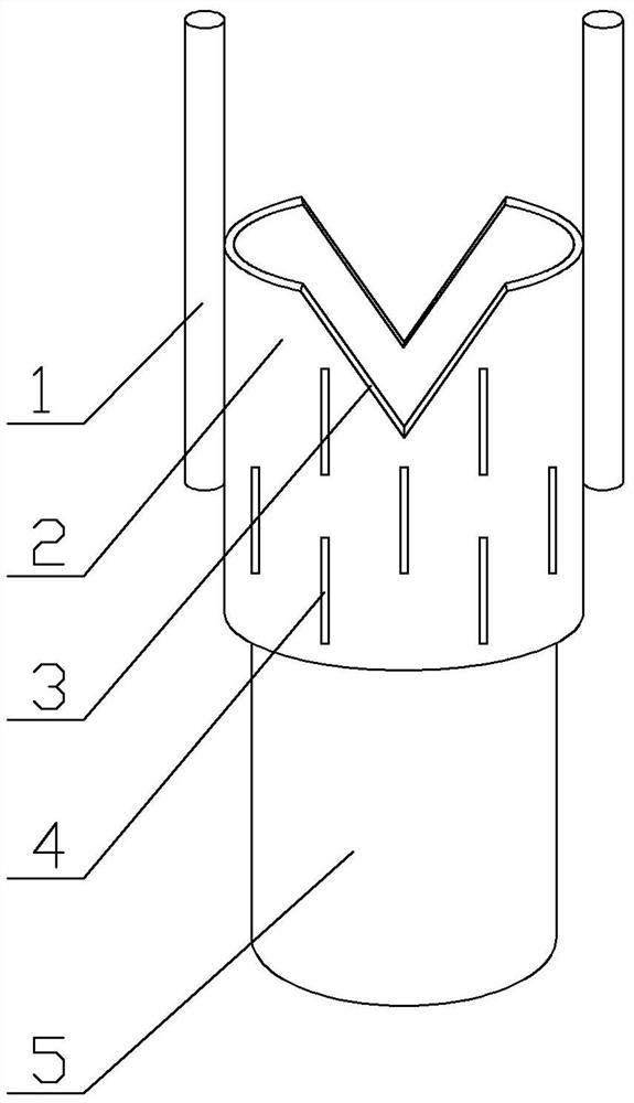
[0017] Embodiment 1: According to figure 1 and figure 2 , a tube head of a grain sampler, which includes a tube head 2 sleeved at the end of the sample tube 5, and the other end of the tube head is a top nozzle; both sides of the tube head are respectively provided with extended Rib 1; the top of the elongated rib is higher than the top nozzle of the pipe head; the front and rear sides of the top nozzle of the pipe head are respectively provided with openings 3; the circumference of the pipe is provided with alternately distributed strip air grooves 4.

[0018] The pipe head is a galvanized metal pipe or a stainless steel pipe, which is welded to one end of the sample pipe.

[0019] The elongated ribs are provided with 2-4 pieces, which are welded on the outer wall of the pipe head, and the top of the elongated ribs is 5-15cm higher than the nozzle at the top of the pipe head.

[0020] When the sample tube is inserted into the bottom of the granary, the extension rib first ...


PUM


Abstract

The invention discloses a grain sampler pipe head which comprises a pipe head connected to the end of a sampling pipe in a sleeving mode, and the other end of the pipe head is a top pipe opening. Lengthening ribs distributed in parallel are arranged on the two sides of the pipe head respectively. The top of each lengthened rib is higher than the top pipe opening of the pipe head; openings are formed in the front side and the rear side of the top pipe opening of the pipe head respectively; and strip-shaped air grooves which are distributed alternately are formed in the circumference of the pipe. The technical problem that the grain sampler pipe head in the prior art is inconvenient to use is effectively solved.

Description

technical field [0001] The invention belongs to the technical field of grain machine equipment, and in particular relates to a tube head of a grain sampler. Background technique [0002] After the grain is put into storage, regular sample testing is required, including multi-point sampling of the upper, middle, and lower layers. Sampling generally uses a fan to drive a high-pressure adsorption type, and the adsorption tube head of the sampling device is extended into different locations and depths for adsorption-type sampling. [0003] At present, the tube head of the sampler adopts a metal round tube, which has a simple and strong structure, but there are many disadvantages in the process of use. The tube head is easy to cause material blockage, if the size is large, the adsorption force will be affected, and there is a technical problem of inconvenient use. Contents of the invention [0004] The purpose of the present invention is to solve the technical problem of inco...

Claims


Application Information

Patent Timeline
Patent Type & Authority Applications(China)
IPC IPC(8): G01N1/10
CPCG01N1/10
Inventor 翟兴海
Owner 中央储备粮日照仓储有限公司
Why Eureka
Try Eureka