Shield of garden pit digging machine

A technology for digging machines and shields, which is applied in the field of garden digging machine shields, can solve the problems of inconvenient use of garden digging machine shields, and achieve the effects of excellent performance, increased specific surface area, and improved compatibility

Inactive Publication Date: 2018-12-28
FUYANG HUAIBANG MACHINERY
View PDF0 Cites 0 Cited by
  • Summary
  • Abstract
  • Description
  • Claims
  • Application Information

AI Technical Summary

Problems solved by technology

[0004] The purpose of the present invention is to solve the technical problem of inconvenient use of the garden digging machine shield in the prior art, and provide a garden digging machine shield to solve the deficiencies of the prior art

Method used


Image

  • Shield of garden pit digging machine
  • Shield of garden pit digging machine
  • Shield of garden pit digging machine

Examples


Embodiment 1

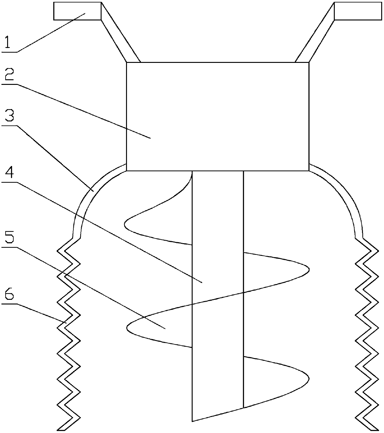
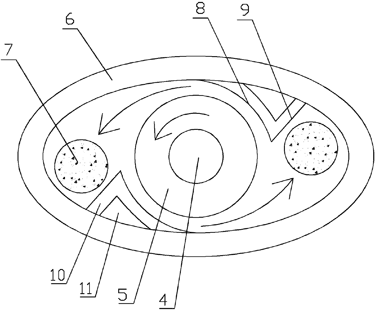
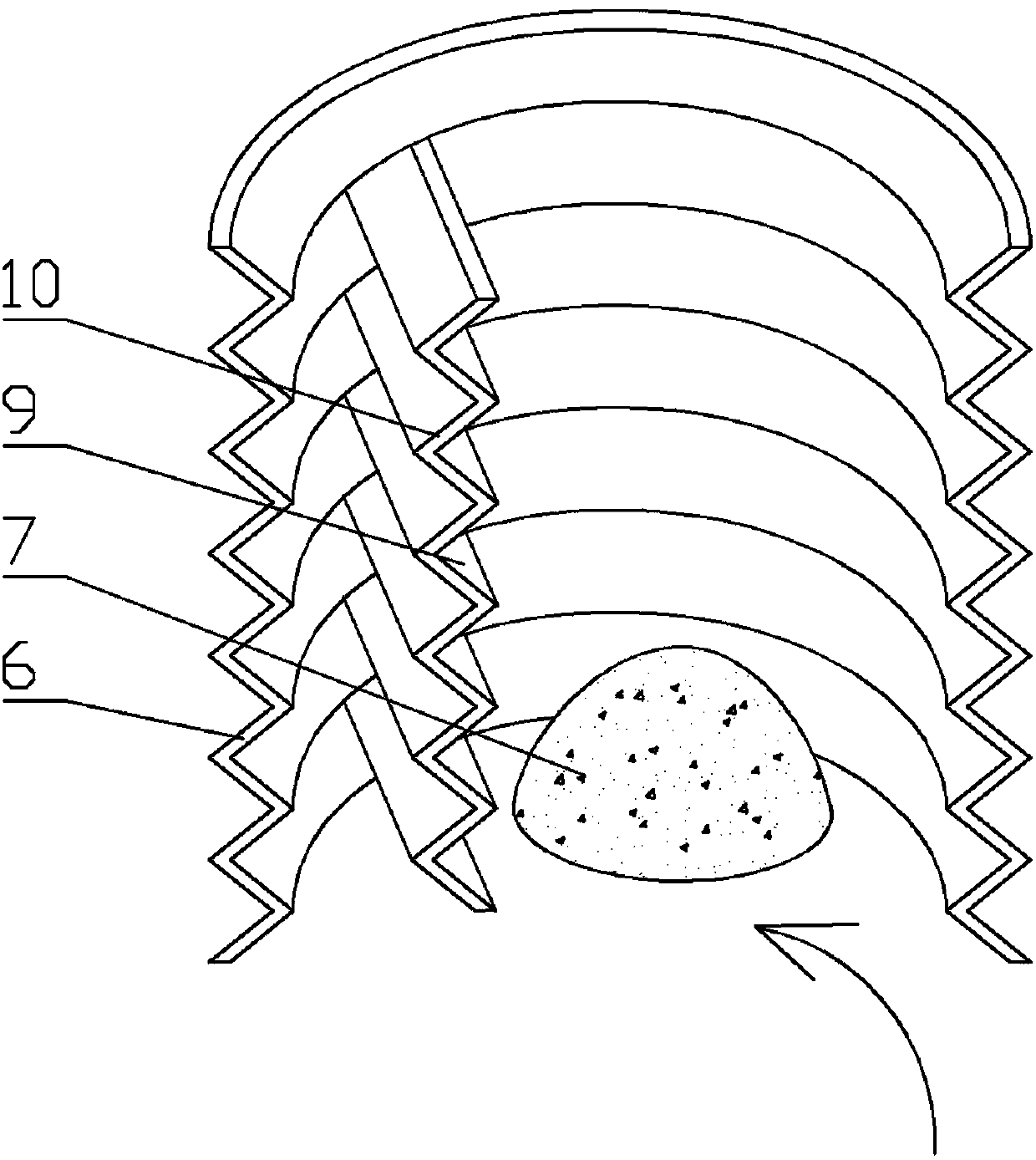
[0029] according to Figure 1-Figure 3 , a garden digging machine shield, which includes a fuel engine 2 with handles 1 at both ends; a transmission shaft 4 for transmission connection is provided below the fuel engine 2; a helical tooth 5 is provided on the transmission shaft; A circle of oval upper cover plate 3 is arranged around the fuel engine, and the drive shaft and helical teeth are located in the middle of the upper cover plate; an oval lower sheath 6 is provided below the upper cover plate; the lower sheath adopts Multi-section folding type; the inside of the lower sheath is provided with two sets of vertically distributed inner lining blocks 10, which are respectively in the small-angle arc ends of the two ends of the lower sheath; the inner lining blocks are multi-section folding like the lower sheath formula; the inner liner block is provided with two surfaces, one is a blocking surface 9 vertically connected with the inner wall of the lower sheath 6, and is oppos...

Embodiment 2

[0038] according to Figure 4 , the structure of this embodiment is basically the same as that of Embodiment 1, the difference is that the transmission shaft and the helical teeth 5 are located at one end of the elliptical upper cover plate 3 and the lower sheath 6; the inner liner block 10 is provided with a set of , located at the other end of the lower sheath 6.

[0039] A group of inner lining blocks 10 are set, and the scattered soil 7 is piled into a pile after excavation, which is convenient for later landfill, and the area covered by the upper cover plate 3 and the lower sheath 6 and its own area are all smaller compared with the prior art , easy to carry and move.

Embodiment 3

[0041] The lower sheath 6 and the inner liner block 10 of the present invention are integrated plastic materials, which are prepared according to the following process:

[0042] 1) Weigh each raw material according to parts by weight, including: 100 parts of ABS resin, 20 parts of phenolic resin, 10 parts of polycarbonate, 10 parts of polyhexamethylene adipate, 10 parts of attapulgite, and 5 parts of polyvinylpyrrolidone , 5 parts of silicon carbide, 3 parts of borax, 3 parts of dioctyl phthalate, 2 parts of glass fiber, 2 parts of silane coupling agent KH-550, 1 part of talcum powder;

[0043] 2) Put silicon carbide and borax in a ball mill for 12 hours, then pass through a 100-mesh sieve, collect the under-sieve, and obtain component A;

[0044]3) Put the attapulgite into a heating furnace for high-temperature calcination. The temperature in the heating furnace is 500°C, and the calcination time is 30 minutes. Take it out, cool it to room temperature, and then add it to twic...


PUM


Abstract

The invention discloses a shield of a garden pit digging machine. The shield comprises a fuel-fired machine provided with handles at two ends; a drive shaft and helical teeth which are in drive connection are arranged below the fuel-fired machine; a circle of oval upper shield plate is arranged on the periphery of the fuel-fired machine, and the drive shaft and the helical teeth are located in themiddle of the upper shield plate; an oval lower jacket is arranged below the upper shield plate; two groups of vertically distributed lining blocks are arranged in the lower jacket and located in small-angle arc ends at two ends of the lower jacket; each lining block comprises two surfaces, one blocking surface is vertically connected with the inner wall of the lower jacket and opposite to the rotation direction of the helical teeth, and the other surface of each lining block is an arc surface and distributed around the helical teeth. The shield is reasonable in structure and convenient to use and can be mounted on the garden pit digging machine in the prior art. The lower jacket freely contacts with fluctuation of the pit digging machine, dug soil is collected from one side, and the technical problem that shields of the garden pit digging machine in the prior art are inconvenient to use is effectively solved.

Description

technical field [0001] The invention belongs to the technical field of garden machinery, and in particular relates to a protective cover for a garden digging machine. Background technique [0002] When trees are planted, two kinds of excavation methods, mechanical and manual, are mainly used. The prior art pit digging machine mainly includes a vertical transmission roller, which is provided with helical teeth, and is provided with a power device and a handle above the transmission roller. This kind of machine uses two people to hold the handle on both sides, and digs holes through the helical teeth, so the work efficiency is high. However, when the excavated soil is splashed in a circular shape with the spiral teeth, it is scattered around. It is inconvenient to gather and fill the soil after planting, and the rotating spiral teeth are highly dangerous. Once the body accidentally touches it during work, the consequences will be disastrous. . [0003] In order to overcome t...

Claims


Application Information

Patent Timeline
IPC IPC(8): A01C5/04
CPCA01C5/04
Inventor 徐春芽应兴军应金火应玉中叶涌水
Owner FUYANG HUAIBANG MACHINERY
Why Eureka
Try Eureka