
An orthopedic support and hanger

A support hanger, orthopedic technology, applied in the field of medical equipment, can solve problems such as affecting blood circulation, having gaps or rotation, increasing patient pain, etc., and achieves the effect of easy installation and use, simple structure, and easy adjustment of angle

Inactive Publication Date: 2018-05-08
汪勇刚
View PDF1 Cites 0 Cited by
  • Summary
  • Abstract
  • Description
  • Claims
  • Application Information

AI Technical Summary

Problems solved by technology

[0003] At present, there are many kinds of external fixators for fractures at home and abroad, including block type, half-moon type, single-rod type, and double-rod type. Causes gaps or rotations on the opposite side due to angulation, and some fractures and displacements after fixation, all of which cannot be adjusted with the fixation frame
Chinese patent CN2035228U discloses a "fracture reduction bone fixer", which uses two threaded bone needles to penetrate the distal and near bone segments of the broken limb, fixes the reset fixer on the broken limb with a set of support frames, and then uses a belt Fasten, this fixer can complete traction, reset, pressurize, and fix at one time, but because it needs to be fastened with a belt, it will affect the blood circulation and increase the pain of the patient, and it cannot make the feet in a comfortable movement, which will easily cause the patient's pain. Fatigue, and the fracture displacement cannot be adjusted. Once the fixation is displaced, it needs to be re-drilled and fixed, which will increase the pain of the patient
[0004] In view of this, it is urgent to optimize the design of the existing technology, and design an orthopedic support and hanger to solve the existing problems in the existing technology that the patient's movement is likely to cause secondary damage to the affected area, and the situation that the doctor and the patient cannot connect the affected area in real time The problem

Method used


Image

  • An orthopedic support and hanger
  • An orthopedic support and hanger
  • An orthopedic support and hanger

Examples


Embodiment 1

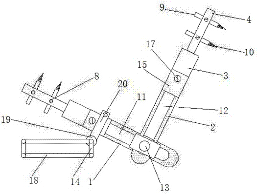
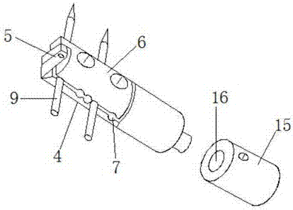
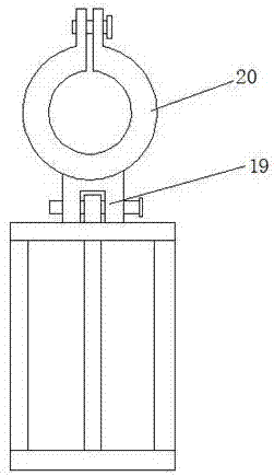
[0032] A support hanger for orthopedics, comprising a first support frame 1 and a second support frame 2, the shape of the first support frame 1 and the second support frame 2 is a U-shaped structure, the first support frame 1 and the second support frame The inside of the frame 2 is provided with a first strip bolt hole 11 and a second strip bolt hole 12, and the setting of the first strip bolt hole 11 and the second strip bolt hole 12 is for the convenience of adjusting the first support frame 1 and the second strip bolt hole 12. The positions between the second support frames 2 make the support and hanger applicable to a wider range.

[0033] The first strip bolt holes 11 and the second strip bolt holes 12 are alternately arranged, and the first strip bolt holes 11 and the second strip bolt holes 12 are fixed by a fastening fixture 13, and the The fastening fixture 13 has a structure in which a fixing block is provided at one end and a nut is provided at the other end, and ...


PUM


Abstract

The invention discloses an orthopedic support hanger. The orthopedic support hanger comprises a first support frame and a second support frame, a first long bolt hole and a second long bolt hole are formed in the first support frame and the second support frame, one end of the first long bolt hole and one end of the second long bolt hole are connected with fixing columns respectively, a bolt hole is formed in one end of each fixing column, each bolt hole is connected with a rotating disk in a bolt joint mode, each rotating disk is fixedly connected with a fixing plate, the upper end of each fixing plate is hinged to a fixing clamp through a hinge chain, a steel pin hole is formed in the contact face of each fixing clamp and the corresponding fixing plate, each fixing clamp and the corresponding fixing plate are fixed through a fixing bolt, the outer side of each fixing column is fixedly provided with a clamping bracket, each clamping bracket and the corresponding fixing column are fixed through a fastening clamp, each clamping bracket is provided with a semicircular support rod, and each semicircular support rod and the corresponding fastening clamp are hinged through a hinge. The orthopedic support hanger is simple in structure, convenient to install and use and worthy of devoting more efforts to popularize. The invention further discloses a usage method of the orthopedic support hanger.

Description

technical field [0001] The invention relates to the technical field of medical devices, in particular to an orthopedic support and hanger and a use method. Background technique [0002] A fracture is a complete or partial break in the continuity of the bone structure. It is more common in children and the elderly, and it also occurs from time to time in young and middle-aged people. After the fracture, it is generally necessary to use a fixation frame for reduction and fixation. After the fixation frame is reset, it is prone to redisplacement due to instability. Therefore, different methods must be used to fix it in a satisfactory position and allow it to heal gradually. After people's limbs are injured and fractured, they cannot immediately and effectively fix the broken bone, especially at night, doctors cannot determine the patient's fracture site, and the wound cannot be treated effectively and properly, especially when moving the patient, it is easier to make the affec...

Claims


Application Information

Patent Timeline
Patent Type & Authority Patents(China)
IPC IPC(8): A61B17/66A61B5/00
CPCA61B5/0002A61B5/4504A61B17/66A61B2017/564
Inventor 汪勇刚唐周舟陈亮
Owner 汪勇刚
Learn More