Pressure container hand hole device

A technology of pressure vessels and hand holes, applied in pressure vessels, fixed-capacity gas storage tanks, mechanical equipment, etc., can solve the problems of air tightness that need to be improved, and achieve the effect of good airtight performance

Inactive Publication Date: 2017-07-21
NANTONG PRATT MACHINERY
View PDF4 Cites 0 Cited by
  • Summary
  • Abstract
  • Description
  • Claims
  • Application Information

AI Technical Summary

Problems solved by technology

Hand hole devices for pressure vessels need good airtightness, and the airtightness of existing hand hole devices needs to be improved

Method used


Image

  • Pressure container hand hole device

Examples


Embodiment Construction

[0007] The present invention will be further described below in conjunction with the accompanying drawings and specific embodiments.

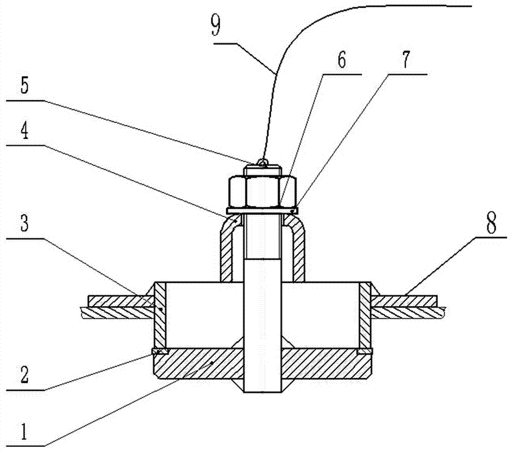
[0008] figure 1 Middle: top plate 1, lining plate 2, joint pipe 3, manhole pressure plate 4, bolt 5, nut 6, washer 7, pressure vessel wall 8, rope body 9.

[0009] A hand hole device for a pressure vessel, the hand hole device includes a top plate 1, a lining plate 2, a joint pipe 3, a manhole pressure plate 4, bolts 5, nuts 6, and a washer 7, the lower end of the bolt 5 is connected to the top plate 1 Welding, the lower end of the joint pipe 3 is connected with the top plate 1, the lining plate 2 is arranged between the top plate 1 and the joint pipe 3, the lining plate 2 is connected with the top plate 1, the joint pipe 3, the joint pipe 3 is welded to the pressure vessel wall 8, the bolt 5 passes through the manhole pressure plate 4, the manhole pressure plate 4 is crimped to the joint pipe 3, the bolt 5 is connected to the The upper end o...


PUM


Abstract

The invention provides a pressure container hand hole device. The hand hole device comprises a top plate, a lining plate, a section hose, a manhole pressing plate, a bolt, a nut and a washer. The lower end of the bolt is fixedly connected with the top plate, the lower end of the section hose is connected with the top plate, the lining plate is arranged between the top plate and the section hose, the lining plate is connected with both the top plate and the section hose, and the section hose is welded to the wall of a pressure container. The pressure container hand hole device has the following beneficial effect that the hand hole device for the pressure container is good in sealing performance.

Description

technical field [0001] The invention relates to a mechanical device, in particular to a hand hole device for a pressure vessel. Background technique [0002] What is the hand hole? The hand hole is an inspection hole, which is used for workers' hands to go deep into the equipment to clean, maintain and overhaul the equipment. The pressure vessel is provided with a hand hole device that requires good airtightness, and the airtightness of the existing hand hole device needs to be improved. Contents of the invention [0003] The invention provides a hand hole device for a pressure vessel. The purpose of designing the device is to provide a hand hole device with good airtightness for the pressure vessel. [0004] The invention provides the following technical solutions: a hand hole device for a pressure vessel, the hand hole device includes a top plate, a lining plate, a section pipe, a manhole pressure plate, bolts, nuts, washers, the lower end of the bolt is connected to th...

Claims


Application Information

Patent Timeline
Patent Type & Authority Applications(China)
IPC IPC(8): F16J12/00F16J13/12
CPCF16J12/00F16J13/12
Inventor 花世军
Owner NANTONG PRATT MACHINERY
Why Eureka
Try Eureka