Steel structure strip sticking mechanism and sticking method

A steel structure and sticking technology, applied in the directions of sending objects, packaging, thin material processing, etc., can solve the problems of difficult to control the degree of fit, time-consuming and laborious, easy to stick irregularly, etc., to achieve automatic cutting and improve work efficiency. , the effect of good tightness

Pending Publication Date: 2019-04-19
江苏睿中轨道交通装备有限公司
View PDF0 Cites 0 Cited by
  • Summary
  • Abstract
  • Description
  • Claims
  • Application Information

AI Technical Summary

Problems solved by technology

It is time-consuming and labor-intensive to stuff sponges and paste stickers manually, and trim the sponges and stickers with inaccurate lengths. It is difficult to control the fit, and it is easy to stick irregularly.

Method used


Image

  • Steel structure strip sticking mechanism and sticking method

Examples


Embodiment 1

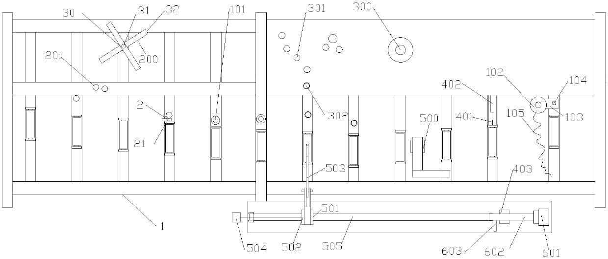
[0041] Embodiment 1, a steel structure sticking mechanism, including a frame 1, and a feeding mechanism on the frame 1, a sponge unwinding mechanism, a spraying device 2, a self-adhesive peeling mechanism, a cutting mechanism, a positioning mechanism, a reset Mechanism, sponge unwinding mechanism, self-adhesive stripping mechanism, and the edge of the feeding mechanism between are provided with a first squeeze roller 101;

[0042] The sponge unwinding mechanism includes a first rotating frame 200 and a first guide roller group 201, which are arranged along the direction of the feeding mechanism;

[0043] The spray device 2 is arranged above the guide rollers near the side of the feeding mechanism in the first guide roller group 201, the spray device 2 is fixedly installed on the column 21, and the bottom of the column 21 is fixedly installed on the frame 1;

[0044] The self-adhesive peeling mechanism includes a second rotating roller 300, a second guide roller group 301, and ...

Embodiment 2

[0054] Embodiment 2, a method for sticking strips of steel structures, the specific steps are as follows:

[0055] 1) Put the steel structure on the conveying mechanism on frame 1 for conveying;

[0056] 2) The sponge unwinding mechanism is opened to unwind the sponge roll;

[0057] 3) The spray device 2 sprays the sponge;

[0058] 4) The wetted sponge is fitted to the groove of the steel structure, and the fitted sponge moves forward with the steel structure, and the first squeeze roller 101 squeezes the sponge;

[0059] 5) The self-adhesive peeling mechanism peels off the self-adhesive;

[0060] 6) Adhering and pasting the colloidal layer of the self-adhesive to the side of the steel structure;

[0061] 7) The positioning device 403 detects that the sponge between adjacent steel structures is in place, and the cutting mechanism starts to cut;

[0062] 8) The pressing device 500 squeezes the steel structure;

[0063] 9) The reset mechanism resets the positioning mechanis...


PUM


Abstract

The invention discloses a steel structure strip sticking mechanism and a sticking method. The method specifically comprises the steps that (1) steel structures are placed on a conveying mechanism on amachine frame to be conveyed; (2) a sponge unwinding mechanism is started, and a sponge roll is unwound; (3) sponge is sprayed through a spraying device; (4) the wetted sponge is stuck to grooves ofthe steel structures, the stuck sponge moves forward along with the steel structures, and the sponge is squeezed through a first squeeze roller; (5) an adhesive sticker is stripped off through an adhesive sticker stripping mechanism; (6) an adhesive layer of the adhesive sticker is attached and stuck to the side surfaces of the steel structures; (7) a cutting mechanism is started for cutting whena positioning device monitors that the sponge between the adjacent steel structures is in place; (8) the steel structures are squeezed through a pressing device; and (9) a positioning mechanism is reset through a reset mechanism.

Description

technical field [0001] The invention relates to a steel structure strip pasting mechanism and a strip pasting method. Background technique [0002] During transportation, the steel structure will inevitably be bumped due to vibration and shaking. The steel structures to be used in subways, bridges and other projects have very high requirements. Therefore, for the steel structures with high requirements in large projects, sponge filling is required, and the surface needs to be covered with self-adhesive. Manually stuffing sponges and sticking stickers, and trimming sponges and stickers with inaccurate lengths, is time-consuming and laborious, and the degree of fit is difficult to control, and it is easy to stick irregularly. Contents of the invention [0003] Purpose of the invention: the purpose of the invention is to provide a kind of [0004] Technical solution: The present invention is a steel structure sticking mechanism, including a frame, and a feeding mechanism on...

Claims


Application Information

Patent Timeline
IPC IPC(8): B65B33/02B65H35/07B65H41/00B65H37/04
CPCB65B33/02B65H35/0033B65H37/04B65H41/00B65H2801/81B65H2701/377Y02P70/10
Inventor 代启宏陈齐嵘施海姜伟亮张军华
Owner 江苏睿中轨道交通装备有限公司
Why Eureka
Try Eureka