Pushbutton Switches and Pushbutton Switch Units
A technology of switch units and buttons, applied in the direction of electric switches, electrical components, contact electrical connections, etc.
- Summary
- Abstract
- Description
- Claims
- Application Information
AI Technical Summary
Problems solved by technology
Method used
Image


Examples
Embodiment approach 1
[0052] according to Figure 1-7, one embodiment of the present invention will be described as follows. In this embodiment, a case where the present invention is applied to an illuminated push button switch mounted on an elevator operation panel will be described as an example.
[0053] However, the push button switch of the present invention is not limited to elevators, and may be applied to push button switches mounted on other equipment.
[0054] (Structure of push button switch 1)
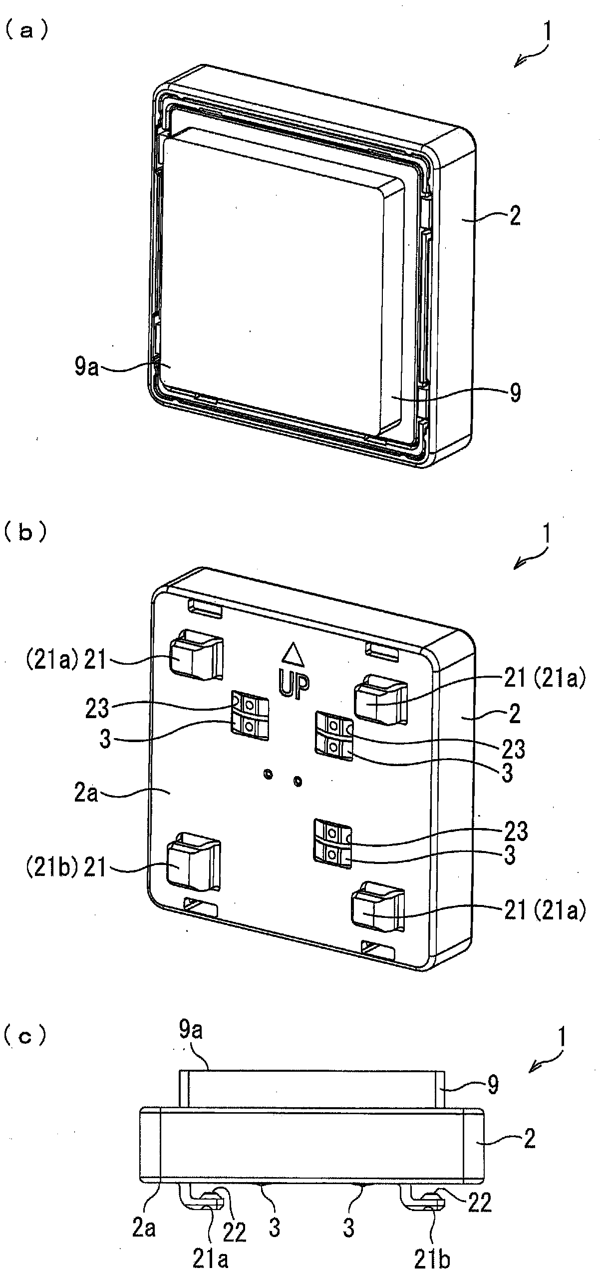
[0055] figure 1 It is a figure which shows the appearance of the push button switch 1 which concerns on embodiment of this invention. Specifically, figure 1 (a) is a front perspective view of the push button switch 1 of this embodiment, figure 1 (b) is figure 1 The perspective view of the bottom surface of the push button switch 1 shown in (a), figure 1 (c) is figure 1 The lower side view of the push button switch 1 shown in (a).
[0056] figure 1 The push button switch 1 shown in (a) ...
Deformed example 1
[0117] Figure 5 (a) and (b) are shown Figure 4 (a) is a perspective view of a modified example of the push button switch unit 110. Specifically, Figure 5 (a) is a front perspective view of the push button switch unit 120, Figure 5 (b) is a bottom perspective view of the push button switch unit 120 .
[0118] like Figure 5 As shown in (a) and (b), two push-button switches 1 can be mounted on the base substrate 100 having a longitudinal direction in a state where two push-button switches 1 are arranged vertically.
[0119] In the push button switch unit 120, when one push switch 1 is damaged and needs to be replaced, only the damaged push switch 1 can be replaced individually.
[0120] Therefore, compared with the conventional structure in which all the pushbutton switches 1 must be replaced together with the base substrate 100, maintenance costs can be reduced.
Deformed example 2
[0122] Image 6 (a) is shown figure 1 Bottom perspective views of modified examples of the push button switch 1 shown in (a) to (c), Image 6 (b) is to show that there is Image 6 (a) is a bottom perspective view of the push button switch unit 130 of the push button switch 1a.
[0123] like Image 6 As shown in (a), the push button switch 1a may be configured to include two substantially parallel L-shaped hooks 21c extending in the depth direction in the L-shaped cross section.
[0124] In this case, as Image 6 As shown in (b), it is only necessary to form the L-shaped hook locking hole 101 c having a shape corresponding to the width of the L-shaped hook 21 c in the base substrate 10 .
[0125] In this way, the shape (width) and number of L-shaped hooks 21 are not limited, and can be appropriately changed according to the purpose.
PUM
 Abstract
Description
Claims
Application Information
 - R&D
- Intellectual Property
- Life Sciences
- Materials
- Tech Scout
- Unparalleled Data Quality
- Higher Quality Content
- 60% Fewer Hallucinations
Browse by: Latest US Patents, China's latest patents, Technical Efficacy Thesaurus, Application Domain, Technology Topic, Popular Technical Reports.
© 2025 PatSnap. All rights reserved.Legal|Privacy policy|Modern Slavery Act Transparency Statement|Sitemap|About US| Contact US: help@patsnap.com