Method for enhancing power distribution box installation efficiency

A distribution box and efficiency technology, applied in the direction of switchgear, electrical components, etc., can solve the problems of increasing the time required for installing the distribution box, increasing the labor intensity of workers, and reducing work efficiency, so as to reduce the labor intensity of workers and improve Efficiency, the effect of improving installation efficiency

Active Publication Date: 2017-07-21
山东万盛电气有限公司
View PDF6 Cites 2 Cited by
  • Summary
  • Abstract
  • Description
  • Claims
  • Application Information

AI Technical Summary

Problems solved by technology

[0013] The purpose of the present invention is to provide a method for improving the efficiency of installing the distribution box, so as to solve the problem that when the height of the distribution box is raised manually, it not only increases the labor intensity of the workers, but also continuously adjusts the position of the distribution box manually, and also increases the installation distribution. The time required for the electric box reduces the problem of work efficiency

Method used


Image

  • Method for enhancing power distribution box installation efficiency
  • Method for enhancing power distribution box installation efficiency

Examples


Embodiment 1

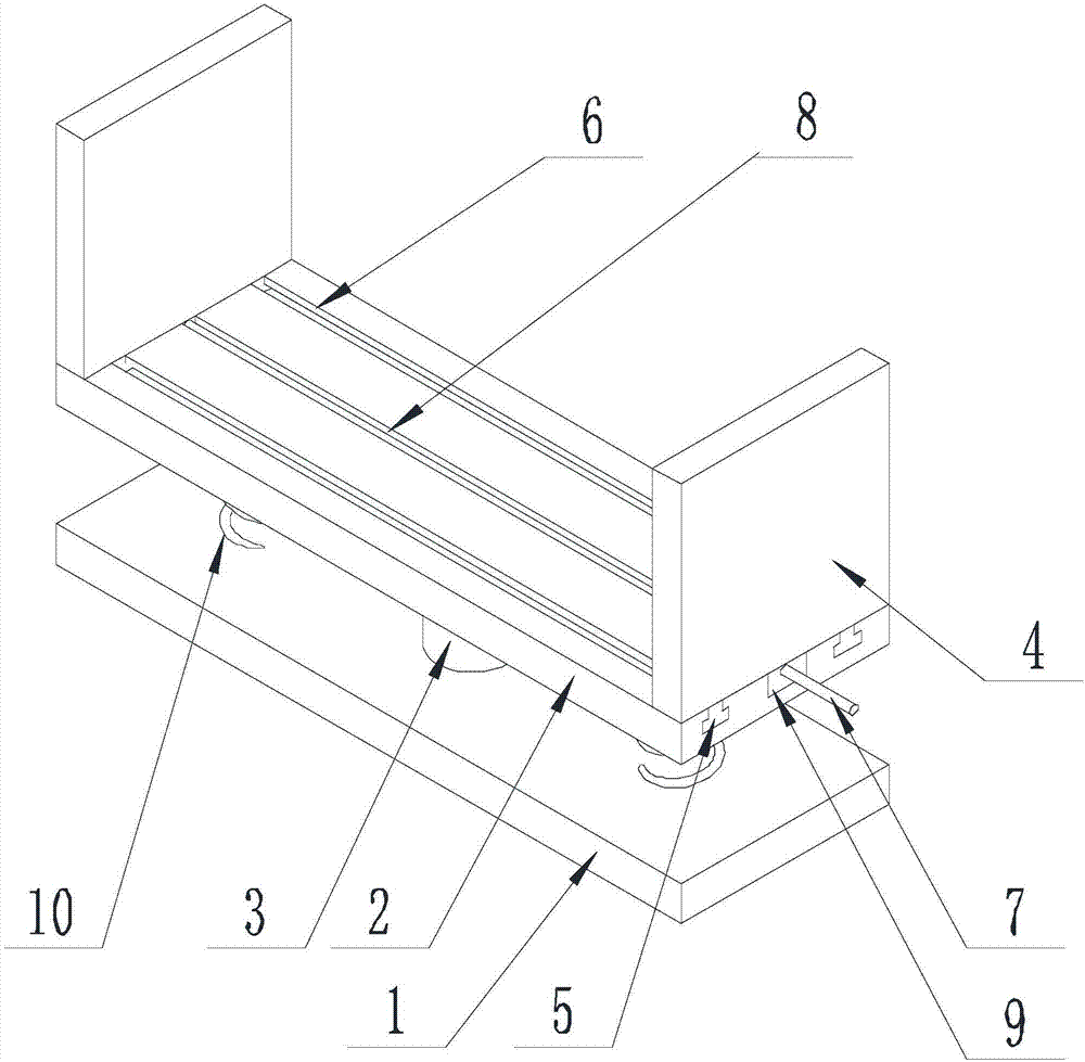
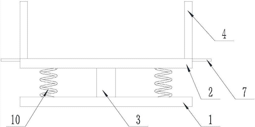
[0042] like Figure 1-Figure 2 As shown, the method for improving the efficiency of installing a distribution box of the present invention includes the following steps:

[0043] Step A Installation: Install the lifting plate 2 on the top of the fixing plate 1 through the telescopic device 3, and then set one plywood 4 on the end of the lifting plate 2 away from the surface of the fixing plate 1, and the other plywood 4 is located on the lifting plate 2. The other end of the board surface, and the splint 4 is connected with the driving device;

[0044] Step B: Place one side of the lifting board 2 in contact with the wall, and make the surface of the fixed board 1 away from the lifting board 2 contact the ground, the plywood 4 is perpendicular to the wall, and then place the distribution box to be installed on the lifting board. on board 2 and between plywood 4;

[0045] Step C: Clamping: start the controller to start the driving device, so that the clamping plates 4 are clos...

Embodiment 2

[0049] The present invention is further described on the basis of Embodiment 1.

[0050] like Figure 1-Figure 2 As shown, the method of the present invention to improve the efficiency of installing a distribution box, the driving device includes a screw 7 and a motor, and a driving block 9 is provided on the end of the splint 4 close to the lifting plate 2, and the lifting plate 2 is far from the fixing plate 1. A screw groove 8 is provided on the surface of the plate, the axis of the screw groove 8 is parallel to the moving track of the splint 4, the screw 7 is located in the screw groove 8, and the axis of the screw 7 is parallel to the moving track of the splint 4;

[0051] One end of the screw 7 is threadedly connected with the driving block 9 of one clamping plate 4, and the other end of the screw 7 is threadedly connected with the driving block 9 of the other clamping plate 4, and the rotation directions of the spiral lines at both ends of the screw 7 are opposite, and ...

Embodiment 3

[0053] The present invention is further described on the basis of Embodiment 1.

[0054] like Figure 1-Figure 2 As shown in the figure, the method of the present invention to improve the efficiency of installing the distribution box, is provided with a guide block 5 on one end of the splint 4 close to the lifting plate 2, and a guide groove 6 is provided on the plate surface of the lifting plate 2 away from the fixed plate 1, The extension axis of the guide groove 6 is parallel to the moving track of the clamping plate 4 , and the guide block 5 is located in the guide groove 6 and moves along the extension axis of the guide groove 6 .

[0055] Further, the size of the opening of the guide groove 6 is smaller than the size of the bottom of the groove, and the cross-sectional size of the guide block 5 is consistent with the cross-sectional size of the guide groove 6 .


PUM


Abstract

The invention discloses a method for enhancing power distribution box installation efficiency. The method comprises the following steps that step A: an elevating plate is installed above a fixing plate through a telescopic device, two clamp plates are arranged on the elevating plate and the clamp plates are connected with a driving device; step B: one side of the elevating plate is contacted with the wall, the clamp plates are perpendicular to the wall and then a power distribution box to be installed is arranged on the elevating plate and positioned between the clamp plates; step C: a controller is started, and the driving device is started so that the clamp plates are enabled to be close to each other until the clamp plates closely clamp the power distribution box arranged on the elevating plate; and step D: the controller is started so that the telescopic device is enabled to contract until the power distribution box arranged on the elevating plate to move to the position of the required height. Compared with the conventional power distribution box installation method through which the power distribution box is manually elevated, the labor intensity of the worker can be reduced, height adjustment of the power distribution box is enabled to be in place in turn and thus the installation efficiency of the power distribution box can be enhanced.

Description

technical field [0001] The invention relates to a method for improving installation efficiency, in particular to a method for improving installation efficiency of a distribution box. Background technique [0002] Power distribution box is a kind of distribution box. The distribution box is divided into power distribution box and lighting distribution box, which is the final equipment of the power distribution system. The distribution box is a low-voltage power distribution device that assembles switchgear, measuring instruments, protective appliances and auxiliary equipment in a closed or semi-closed metal box or on the screen according to the electrical wiring requirements. During normal operation, the circuit can be switched on or off by means of manual or automatic switches. When the distribution box fails or does not operate normally, the circuit is cut off or alarmed by means of protective appliances. The distribution box can display various parameters in operation b...

Claims


Application Information

Patent Timeline
IPC IPC(8): H02B3/00
CPCH02B3/00
Inventor 梁波
Owner 山东万盛电气有限公司
Why Eureka
Try Eureka