

Wide-angle imaging lens assembly
A lens group and imaging technology, applied in optical components, optics, instruments, etc., can solve the problems of large aberration, long total length of lens group, large distortion, etc.
- Summary
- Abstract
- Description
- Claims
- Application Information
AI Technical Summary
Problems solved by technology
Method used
Image

Examples
no. 1 example
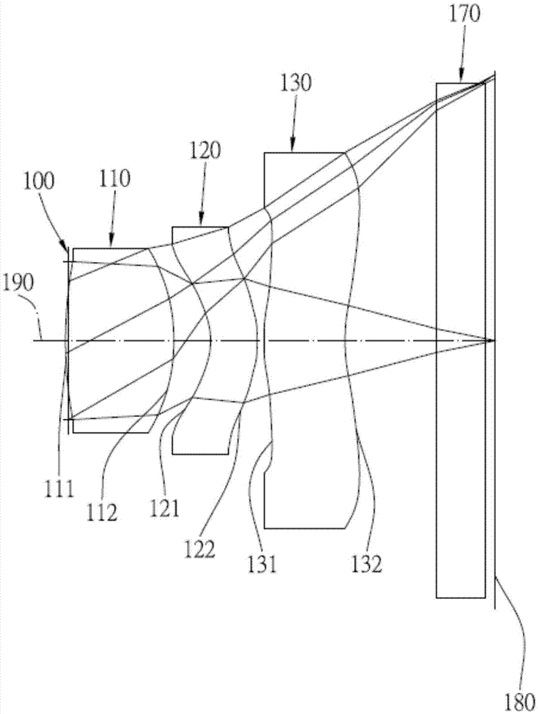
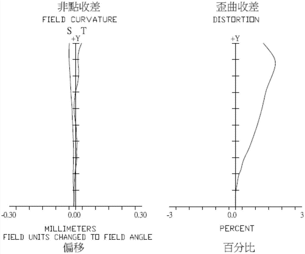
[0058] Please refer to Figure 1A and Figure 1B ,in Figure 1A A schematic diagram showing a wide-angle imaging lens group according to the first embodiment of the present invention, Figure 1B From left to right are the spherical aberration, astigmatism and distortion curves of the wide-angle imaging lens set of the first embodiment. Depend on Figure 1A It can be seen that the wide-angle imaging lens group includes an aperture 100 and an optical group, and the optical group includes a first lens 110, a second lens 120, a third lens 130, and an infrared filter assembly 170 from the object side to the image side in sequence. , and the imaging surface 180, wherein there are three lenses with refractive power in the wide-angle imaging lens group. The aperture 100 is disposed between the image-side surface 112 of the first lens 110 and the subject.
[0059] The first lens 110 has a positive refractive power and is made of plastic material. Its object-side surface 111 is convex...
no. 2 example
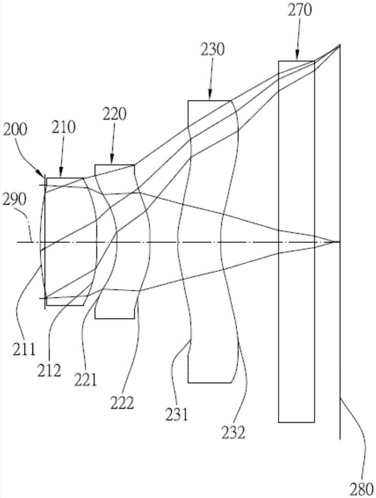
[0086] Please refer to Figure 2A and Figure 2B ,in Figure 2A A schematic diagram showing a wide-angle imaging lens group according to a second embodiment of the present invention, Figure 2B From left to right are the spherical aberration, astigmatism and distortion curves of the wide-angle imaging lens set of the second embodiment. Depend on Figure 2A It can be seen that the wide-angle imaging lens system includes a diaphragm 200 and an optical group, and the optical group includes a first lens 210, a second lens 220, a third lens 230, and an infrared filter assembly 270 from the object side to the image side in sequence. , and the imaging surface 280, wherein there are three lenses with refractive power in the wide-angle imaging lens group. The aperture 200 is disposed between the image-side surface 212 of the first lens 210 and the subject.
[0087] The first lens 210 has positive refractive power and is made of plastic material. Its object-side surface 211 is conv...
no. 3 example
[0099] Please refer to Figure 3A and Figure 3B ,in Figure 3A A schematic diagram showing a wide-angle imaging lens group according to a third embodiment of the present invention, Figure 3BFrom left to right are the spherical aberration, astigmatism and distortion curves of the wide-angle imaging lens set of the third embodiment. Depend on Figure 3A It can be seen that the wide-angle imaging lens system includes a diaphragm 300 and an optical group, and the optical group includes a first lens 310, a second lens 320, a third lens 330, and an infrared filter assembly 370 from the object side to the image side in sequence. , and an imaging surface 380, wherein there are three lenses with refractive power in the wide-angle imaging lens group. The aperture 300 is disposed between the image-side surface 312 of the first lens 310 and the subject.
[0100] The first lens 310 has a positive refractive power and is made of plastic material. Its object-side surface 311 is convex...
PUM
 Abstract
Description
Claims
Application Information