
Three-piece type infrared single-wavelength lens group

An infrared, single-wavelength technology, applied in optical components, optics, instruments, etc., can solve the problems of changing the focal length of the lens group, poor light transmittance of the material, the depth detection accuracy of the game machine, and the inability to meet the depth sensing effect of 3D games, etc.

Active Publication Date: 2020-06-12
NEWMAX TECH
View PDF10 Cites 0 Cited by
  • Summary
  • Abstract
  • Description
  • Claims
  • Application Information

AI Technical Summary

Problems solved by technology

[0003] Among them, the applicant previously proposed a number of lens sets related to infrared wavelength reception, but the current game consoles are mainly for more three-dimensional, real and more immersive 3D games, and the current or previous lens sets of the applicant are all based on 2D plane game detection is a requirement, so that it cannot meet the depth sensing function that 3D games focus on
[0004] Furthermore, for the infrared receiving and sensing lens sets dedicated to game consoles, plastic lenses are used in pursuit of low cost. First, the poor light transmission of the material is one of the key factors affecting the lack of depth detection accuracy of game consoles. Second, plastic lenses are easy to detect. Because the ambient temperature is too hot or too cold, the focal length of the lens group changes and cannot accurately focus detection. As mentioned above, the current infrared wavelength receiving lens group cannot meet the two technical issues of accurate sensing of depth and distance in 3D games.

Method used


Image

  • Three-piece type infrared single-wavelength lens group
  • Three-piece type infrared single-wavelength lens group
  • Three-piece type infrared single-wavelength lens group

Examples


Embodiment 1

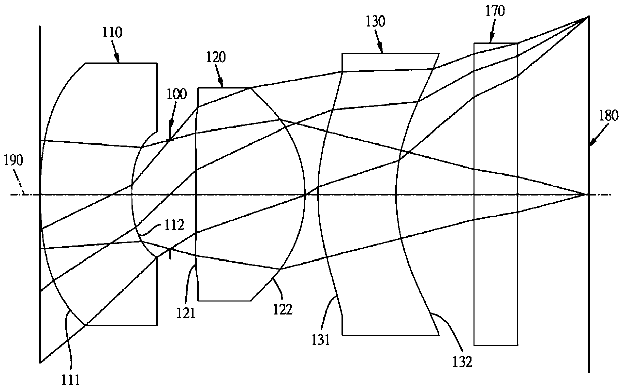
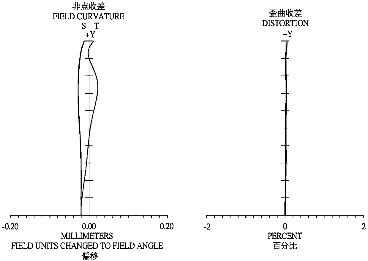
[0070] Such as Figure 1A , Figure 1B shown, where Figure 1A A schematic diagram showing a three-piece infrared single-wavelength lens group according to Embodiment 1 of the present invention, Figure 1B From left to right are the image plane curvature and distortion aberration curves of the three-piece infrared single-wavelength lens set of the first embodiment. Such as Figure 1A As shown, the three-piece infrared single-wavelength lens group includes an aperture 100 and an optical group, and the optical group includes a first lens 110, a second lens 120, a third lens 130, and an infrared filter in sequence from the object side to the image side. The optical filter 170 and the imaging surface 180, wherein there are three lenses (110, 120, 130) with refractive power in the three-piece infrared single-wavelength lens group. The aperture 100 is disposed between the first lens 110 and the second lens 120 .

[0071] The first lens 110 has a negative refractive power and is ma...

Embodiment 2

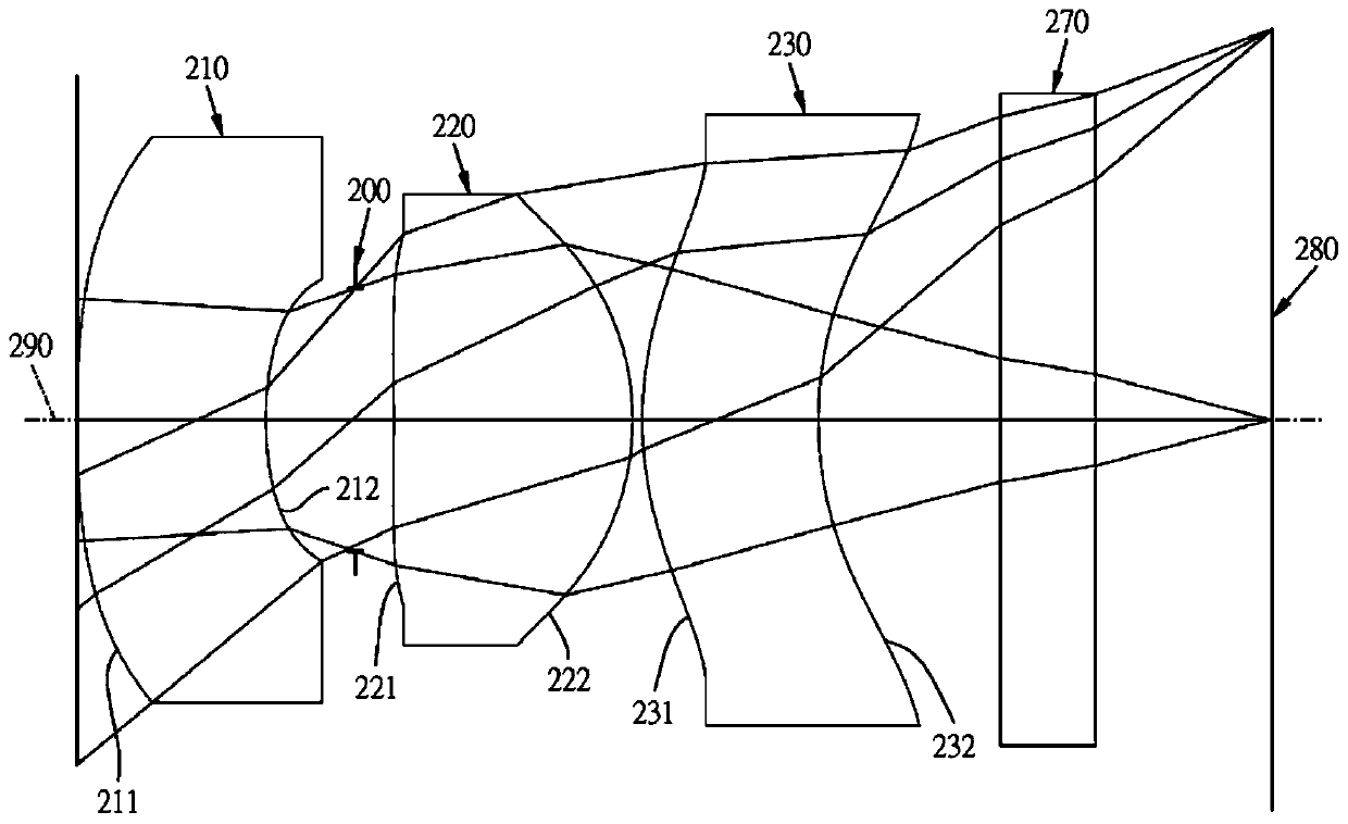
[0099] Such as Figure 2A , Figure 2B shown, where Figure 2A A schematic diagram showing a three-piece infrared single-wavelength lens group according to Embodiment 2 of the present invention, Figure 2B From left to right are the image plane curvature and distortion aberration curves of the three-piece infrared single-wavelength lens set of the second embodiment. Depend on Figure 2A It can be seen that the three-piece infrared single-wavelength lens group includes an aperture 200 and an optical group, and the optical group includes a first lens 210, a second lens 220, a third lens 230, an infrared filter filter and an infrared filter in sequence from the object side to the image side. The optical sheet 270 and the imaging surface 280, wherein the three lenses (210, 220, 230) with refractive power in the three-piece infrared single-wavelength lens group. The aperture 200 is disposed between the first lens 210 and the second lens 220 .

[0100]The first lens 210 has a n...

Embodiment 3

[0113] Such as Figure 3A , Figure 3B shown, where Figure 3A A schematic diagram showing a three-piece infrared single-wavelength lens group according to Embodiment 3 of the present invention, Figure 3B From left to right are the image plane curvature and distortion aberration curves of the three-piece infrared single-wavelength lens set of the third embodiment. Depend on Figure 3A It can be seen that the three-piece infrared single-wavelength lens group includes an aperture 300 and an optical group, and the optical group includes a first lens 310, a second lens 320, a third lens 330, an infrared filter filter and an infrared filter in sequence from the object side to the image side. The optical sheet 370 and the imaging surface 380, wherein the three lenses (310, 320, 330) with refractive power in the three-piece infrared single-wavelength lens group. The aperture 300 is disposed between the first lens 310 and the second lens 320 .

[0114] The first lens 310 has a n...


PUM


Abstract

The invention relates to a three-piece type infrared single-wavelength lens group, which sequentially comprises a first lens, an aperture, a second lens and a third lens from the object side to the image side; the first lens has negative refractive power, a convex face is arranged, near an optical axis, on the object side surface of the first lens, a concave surface is arranged, near the optical axis, on the image side surface of the first lens and at least one of the object side surface and the image side surface of the first lens is a non-spherical face; the second lens has positive refractive power, a convex face is arranged, near the optical axis, of the image side surface of the second lens and at least one surface of the object side surface and the image side surface of the second lens is a non-spherical face; and the third lens has refractive power, a convex face is arranged, near an optical axis, on the object side surface of the third lens, a concave surface is arranged, nearthe optical axis, on the image side surface of the third lens and at least one of the object side surface and the image side surface of the third lens is a non-spherical face. Therefore, the lens group has the effects of angle drawing improvement, large aperture, short lens length and less distortion.

Description

technical field [0001] The invention relates to lens groups, in particular to a miniaturized three-piece infrared single-wavelength lens group applied to electronic products. Background technique [0002] Today's digital imaging technology is constantly innovating and changing, especially in the miniaturization of digital carriers such as digital cameras and mobile phones, and the photosensitive components such as CCD or CMOS are also required to be more miniaturized. In the application of infrared focusing lenses, in addition to using In the field of photography, it has also been widely used in the infrared receiving and sensing field of game machines in recent years. In order to make the game machine sense a wider range of users, most of the lens groups that receive infrared wavelengths are wide-angle lenses with larger picture angles. group is dominant. [0003] Among them, the applicant previously proposed a number of lens sets related to infrared wavelength reception, ...

Claims


Application Information

Patent Timeline
IPC IPC(8): G02B13/00G02B13/14G02B13/18
CPCG02B13/0035G02B13/146G02B13/18
Inventor 吴昆叡
Owner NEWMAX TECH
Learn More