Bridge equipment

A technology for equipment and bridges, applied in the field of bridge equipment, can solve problems such as weak plug connection, interruption of power supply, electric shock accidents, etc., so as to reduce the occurrence of electric shock accidents, improve connection stability, and improve work efficiency.

Inactive Publication Date: 2017-07-25
PUJIANG KECHUANG IMPORT & EXPORT
View PDF10 Cites 9 Cited by
  • Summary
  • Abstract
  • Description
  • Claims
  • Application Information

AI Technical Summary

Problems solved by technology

[0002] Electrified maintenance equipment is often used in the bridge maintenance process. However, in some bridge constructions, there are fewer preset power supply seats and they are all fixed. This makes it difficult to connect the power supply. In the prior art, one or more terminal boards are generally used to lengthen the connection to reach the ideal power supply insertion length. It is extremely inconvenient to put it away. At the same time, during the use of power supply, due to the weak plug connection, it is easy to cause loose plug connection, resulting in poor contact and interruption of power supply. It is also very easy to induce electric shock accidents under human careless touch. potential safety hazards and need to be improved

Method used


Image

  • Bridge equipment
  • Bridge equipment
  • Bridge equipment

Examples


Embodiment Construction

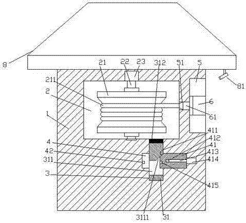
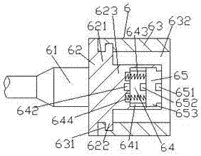
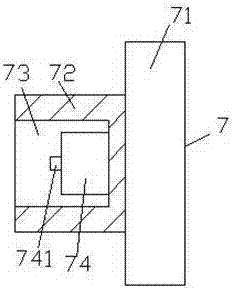
[0023] Such as Figure 1-Figure 8 As shown, a bridge device of the present invention includes a housing 1 and a port piece 7 provided on the maintenance equipment. The housing 1 is provided with a housing chamber 2, and the housing on the right side of the housing chamber 2 1. An installation groove 5 is provided in the outer end surface, and a communication hole 51 is provided between the installation groove 5 and the accommodation chamber 2. The inner bottom wall on the right side of the accommodation chamber 2 is provided with a top and the accommodation chamber 2 connected first sliding groove 3, the center of the first sliding groove 3 is provided with a second sliding groove 4 and communicated with the first sliding groove 3, and the accommodating cavity 2 is provided with a rotating shaft 22 , the top of the rotating shaft 22 is connected with the first driver 23, the rotating shaft 22 is fixed with a reel 21, the reel 21 is provided with a cable 211, and the installati...


PUM


Abstract

The invention discloses bridge equipment. The bridge equipment comprises a shell and a port part arranged on maintenance equipment, wherein an accommodating cavity is formed in the shell; a placement groove is formed in the outer side end plane of the shell on the right side of the accommodating cavity; a connecting hole is formed between the placement groove and the accommodating cavity; a first sliding groove, the top of which is connected with the accommodating cavity, is formed in the inner bottom wall on the right side of the accommodating cavity; a second sliding groove is formed in the center of the first sliding groove in a run-through manner, and the second sliding groove is connected with the first sliding groove; a rotary shaft is arranged in the accommodating cavity; the top of the rotary shaft is connected with a first driver in a matching manner; a reel is fixedly arranged on the rotary shaft; the reel is wound with a cable; a power-on end is arranged in the placement groove; an inserting column, connected with the connecting hole in a matching manner, is arranged on the left side end plane of the power-on end; the left side end plane of the inserting column is fixedly connected with the cable; a jointing block is arranged in the power-on end; and a bump is arranged on the right side end plane of the jointing block. The bridge equipment is simple in structure, convenient to operate, stable and firm in connection, and high in safety.

Description

technical field [0001] The invention relates to the technical field of bridge facilities, in particular to bridge equipment. Background technique [0002] Electrified maintenance equipment is often used in the bridge maintenance process. However, in some bridge constructions, there are fewer preset power supply seats and they are all fixed. This makes it difficult to connect the power supply. In the prior art, one or more terminal boards are generally used to lengthen the connection to reach the ideal power supply insertion length. It is extremely inconvenient to put it away. At the same time, during the use of power supply, due to the weak plug connection, it is easy to cause loose plug connection, resulting in poor contact and interruption of power supply. It is also very easy to induce electric shock accidents under human careless touch. safety hazards and needs to be improved. Contents of the invention [0003] The technical problem to be solved by the present invent...

Claims


Application Information

Patent Timeline
Patent Type & Authority Applications(China)
IPC IPC(8): H01R13/72H01R13/44H01R13/629H01R13/639
CPCH01R13/72H01R13/44H01R13/629H01R13/639
Inventor 叶彩
Owner PUJIANG KECHUANG IMPORT & EXPORT
Why Eureka
Try Eureka