Eureka AIR delivers breakthrough ideas for toughest innovation challenges, trusted by R&D personnel around the world.

Bending mold

A technology of bending dies and bending knives, which is applied in the field of stamping, can solve the problems of high precision of the wedge 2 itself, high cost of mold development, complicated installation and debugging, etc., and achieves simple and exquisite structure, low development cost, and improved forming The effect of precision

Inactive Publication Date: 2017-07-28
ANHUI JIANGHUAI AUTOMOBILE GRP CORP LTD
View PDF0 Cites 5 Cited by
  • Summary
  • Abstract
  • Description
  • Claims
  • Application Information

AI Technical Summary

Problems solved by technology

However, the oblique wedge 2 in the prior art has a large volume, which leads to high mold development costs; meanwhile, the oblique wedge 2 has high precision requirements, and its installation and debugging are complicated, time-consuming and laborious

Method used


Image

  • Bending mold
  • Bending mold
  • Bending mold

Examples


Embodiment Construction

[0035] Embodiments of the present invention are described in detail below, examples of which are shown in the drawings, wherein the same or similar reference numerals designate the same or similar elements or elements having the same or similar functions throughout. The embodiments described below by referring to the figures are exemplary only for explaining the present invention and should not be construed as limiting the present invention.

[0036] Figure 4 The schematic diagram of the structure of the bending die provided by the embodiment of the present invention, Figure 5 The explosion diagram of the bending die provided for the embodiment of the present invention, Image 6 The state diagram of the bending die provided for the embodiment of the present invention before forming the plate, Figure 7 The state diagram of the bending die provided for the embodiment of the present invention after forming the plate, Figure 8 The state diagram of the bending die during the...


PUM


Abstract

The invention discloses a bending mold. The bending mold comprises a pressing block, a base, a male mold core and two bending cutter blocks symmetrically arranged. The pressing block is fixedly arranged on an upper mold seat. The base is fixedly arranged on a lower mold seat. A support seat is fixedly arranged on the base. A groove is formed in the middle position of the support seat. Open stoppers are arranged at the two ends of the support seat. The male mold core is fixedly arranged in the groove. The width of the male mold core is smaller than that of the groove. The two bending cutter blocks are rotationally connected with the open stoppers. Each bending cutter block comprises a forming end and a fixing end. The forming ends are arranged below the pressing block. The fixing ends are connected with the base through springs. The bending mold is simple and compact in structure and low in development cost; and by arranging the detachable male mold core and the bending cutter blocks capable of achieving automatic return, positioning of a plate material before forming is facilitated, the continuity of plate material forming is guaranteed, and the forming precision of the plate material is improved.

Description

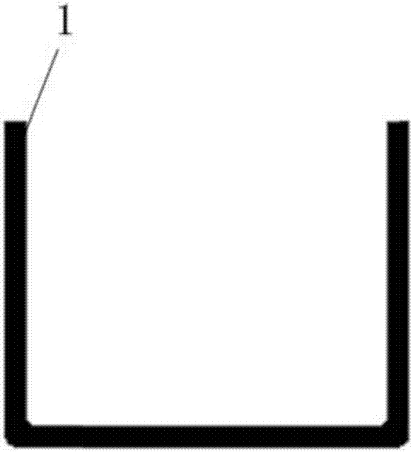
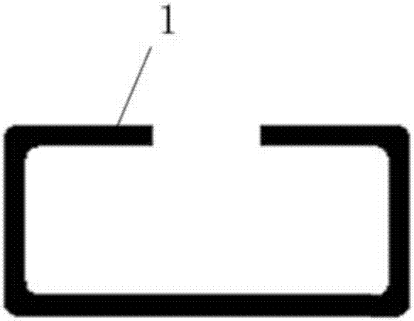
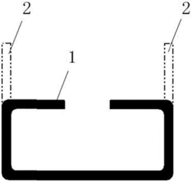
technical field [0001] The invention relates to the technical field of stamping, in particular to a bending die. Background technique [0002] The flanging process is one of the key processes in the sheet stamping process. figure 1 is the state diagram of the panel before flanging, figure 2 is the state diagram of the panel after flanging, image 3 For the schematic diagram of the panel flanging process, please also refer to Figure 1 to Figure 3 , in the prior art, in order to figure 1 The plate in 1 is processed into figure 2 In the state, the oblique wedge 2 is usually set on the position where the plate 1 needs to be bent, such as image 3 The position shown by the dotted line in the figure; by driving the wedges 2 to move toward each other, the bending of the panel 1 is realized. However, the oblique wedge 2 in the prior art has a relatively large volume, which leads to high mold development costs; meanwhile, the oblique wedge 2 has high requirements on its own ...

Claims


Application Information

Patent Timeline
Patent Type & Authority Applications(China)
IPC IPC(8): B21D19/10B21D37/10B21D43/00
CPCB21D19/10B21D37/10B21D43/003
Inventor 阮林凡李辉高双明李昂陈世涛丁文军赖荣胜徐肖何鹏申
Owner ANHUI JIANGHUAI AUTOMOBILE GRP CORP LTD
Why Eureka
Eureka Blog
Learn More