Liquid ejection module and liquid ejection head
A liquid ejection head and liquid technology, which is applied in the direction of printing and inking devices, can solve the problems of not being able to obtain the expected results and lower printing density, and achieve the effect of suppressing uneven printing
- Summary
- Abstract
- Description
- Claims
- Application Information
AI Technical Summary
Problems solved by technology
Method used
Image
Examples
no. 1 approach
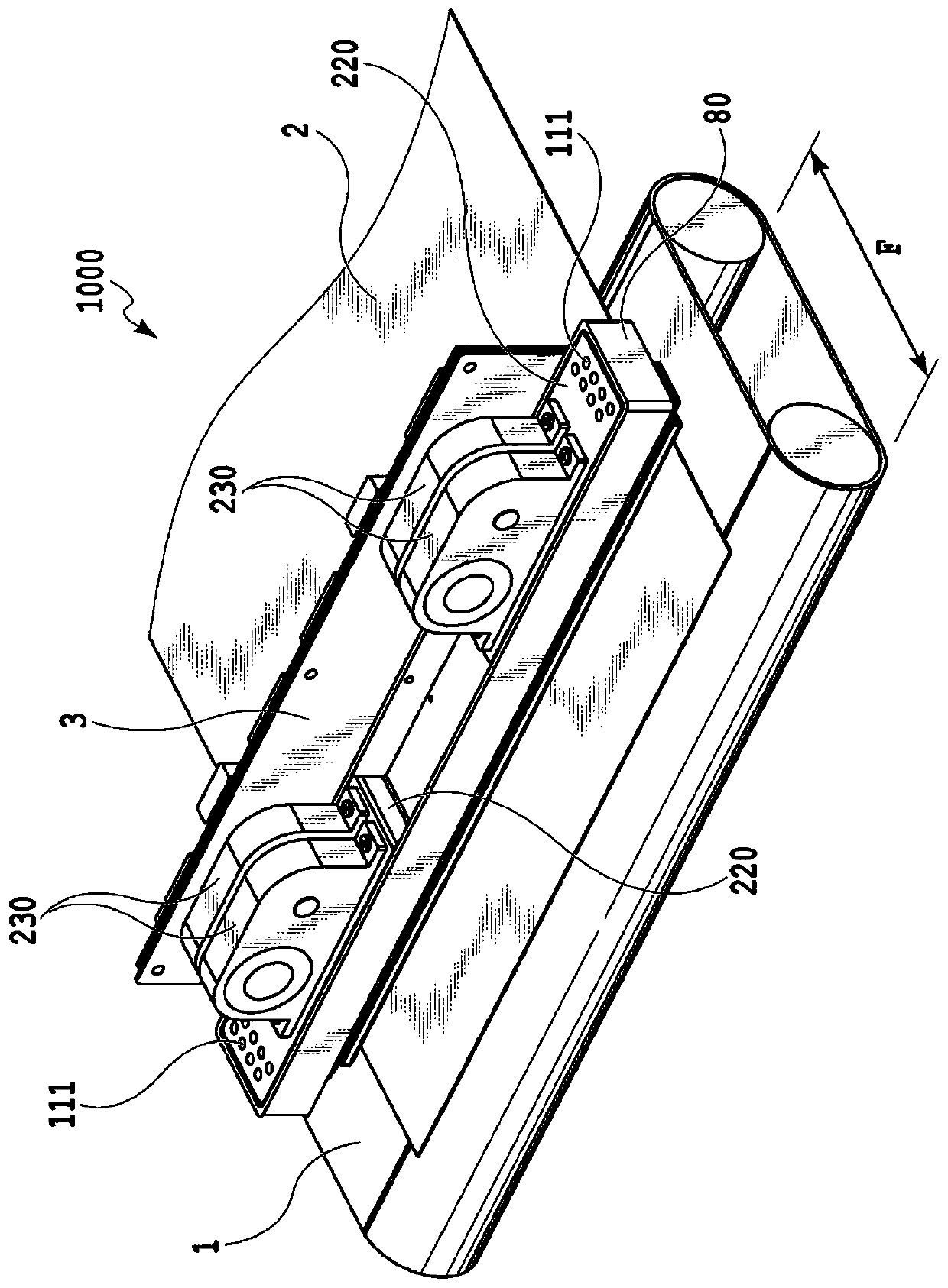
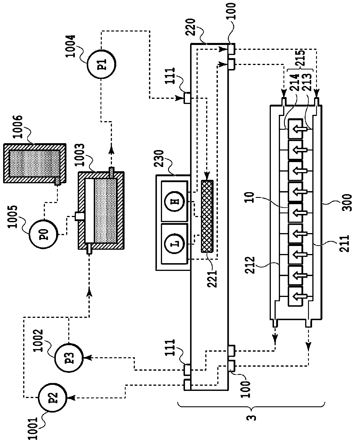
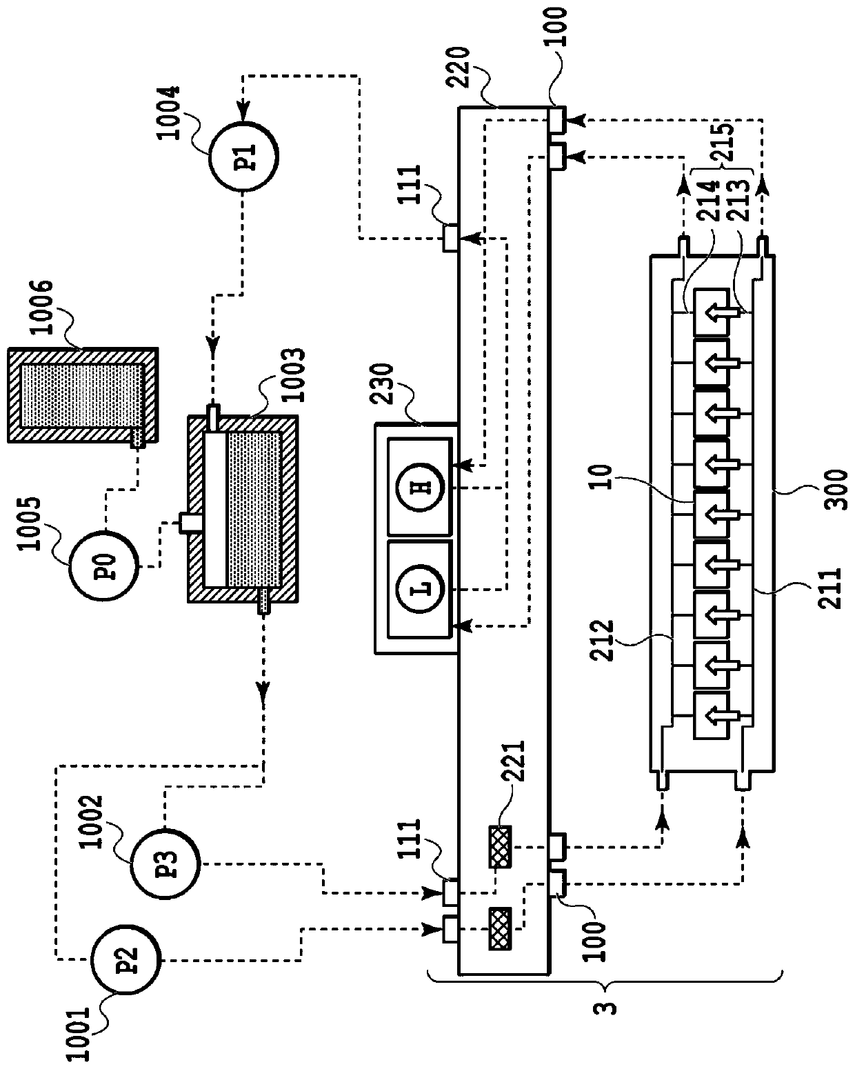
[0186] Hereinafter, a first embodiment of the present invention will be described with reference to the drawings. In addition, since the basic configuration of the present embodiment is the same as that of the first application example, only the characteristic points will be described below.
[0187] Figure 22A It is a perspective view showing the liquid ejection module 200 of the printing apparatus 1000 of this embodiment. The liquid ejection module 200 has a configuration in which the printing element substrate 10 and the flexible circuit board 40 are arranged on the supporting member 30 . Figure 22B It is an exploded perspective view showing the liquid ejection module 200 . The terminal 16 of the printing element substrate 10 and the terminal 41 of the flexible circuit board 40 are electrically connected to each other by metal wiring (not shown), and the connection portion is covered by the sealing member 110 for protection. The supporting member 30 is provided with a ...
no. 2 approach
[0207] Hereinafter, a second embodiment of the present invention will be described with reference to the drawings. In addition, since the basic configuration of the present embodiment is the same as that of the first application example, only the characteristic points will be described below.
[0208] Figure 25A is a diagram showing the printing element substrate 400 of this embodiment, Figure 25B is an exploded perspective view showing the liquid ejection module 500, Figure 25C It is a diagram showing the liquid ejection head 600 in which the liquid ejection module 500 is disposed.
[0209] In the configuration of the first embodiment, the longest distance from the opening 21 to the ejection port 13 is different between the ejection port rows. For example, as from Figure 23A As understood, from the comparison between the distance between the opening 21 at the right end of the figure of the discharge port row 14a and the discharge port 13 and the distance between the o...
no. 3 approach
[0216] Hereinafter, a third embodiment of the present invention will be described with reference to the drawings. In addition, since the basic configuration of the present embodiment is the same as that of the first application example, only the characteristic points will be described below.
[0217] Figures 26A to 26C is a diagram showing the structure of the printing element substrate 10 . Figure 26A shows the overall outline of the printing element substrate 10, Figure 26B yes Figure 26A Enlarged view of part XXVIb of Figure 26C is along Figure 26A A cross-sectional view taken along line XXVIc-XXVIc.
[0218] In this embodiment, the structure of the path for supplying ink to the ejection port is different from that of the above-described embodiment. In the above-described embodiments, the configuration in which the passage for supplying ink to the ejection port and the passage for recovering ink from the ejection port are divided has been described. However, in...
PUM
 Abstract
Description
Claims
Application Information
 - R&D Engineer
- R&D Manager
- IP Professional
- Industry Leading Data Capabilities
- Powerful AI technology
- Patent DNA Extraction
Browse by: Latest US Patents, China's latest patents, Technical Efficacy Thesaurus, Application Domain, Technology Topic.
© 2024 PatSnap. All rights reserved.Legal|Privacy policy|Modern Slavery Act Transparency Statement|Sitemap


