Molded motor
A motor and molding technology, applied in the direction of casing/housing/support, electrical components, electromechanical devices, etc., can solve problems such as thermal degradation of molding resins
- Summary
- Abstract
- Description
- Claims
- Application Information
AI Technical Summary
Problems solved by technology
Method used
Image

Examples
Embodiment approach 1
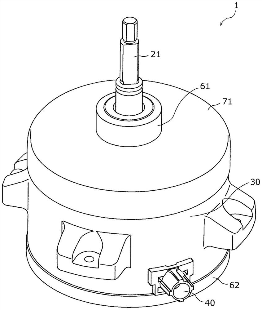
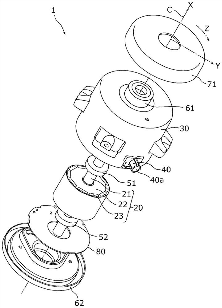
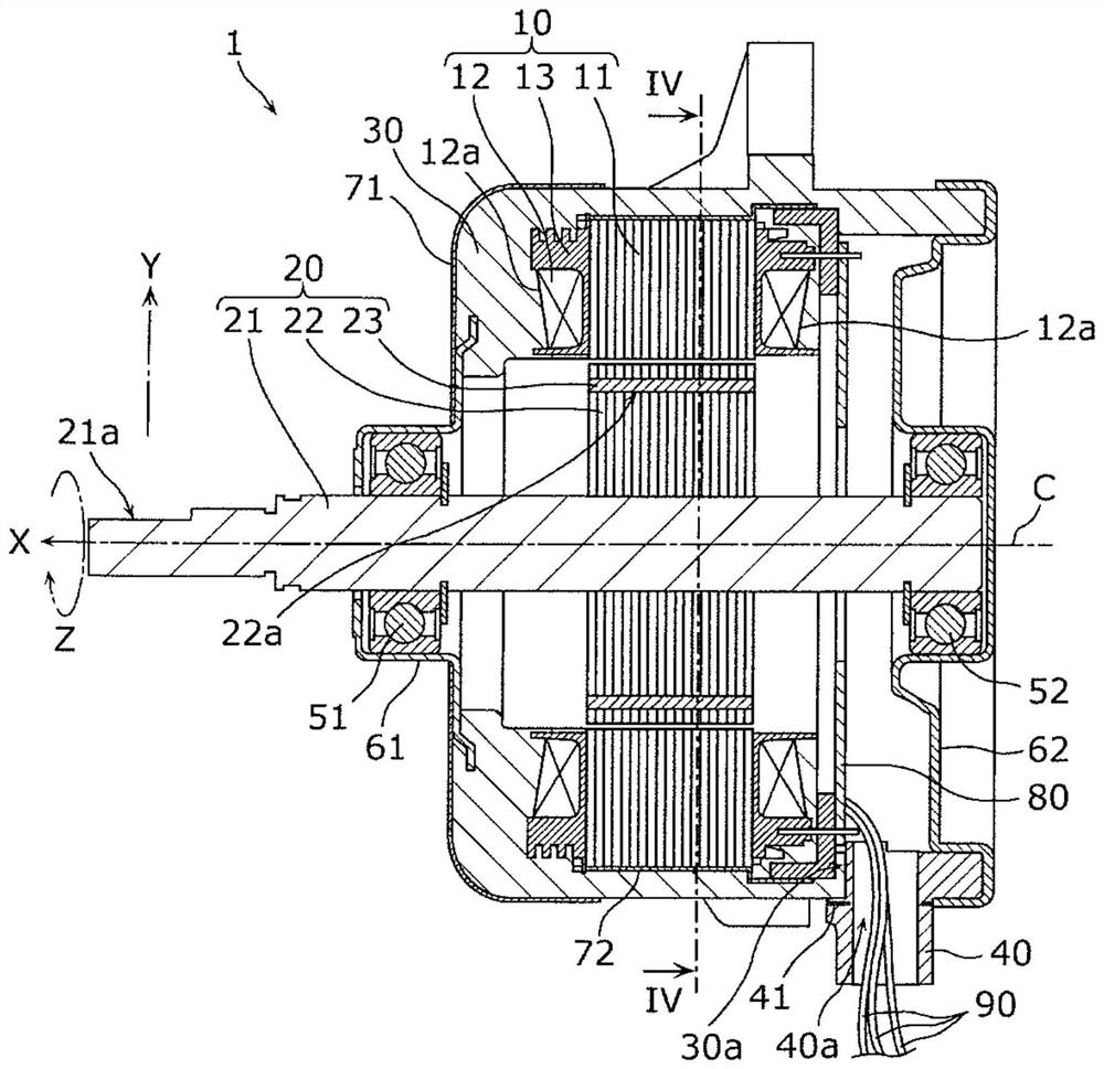
[0048] First, use Figure 1 ~ Figure 4 The overall structure of the molded motor 1 according to Embodiment 1 will be described. figure 1 It is a perspective view of the molded motor 1 of Embodiment 1. figure 2 is an exploded perspective view of the molded motor 1 . image 3 is a sectional view of the molded motor 1 . Figure 4 is the molded motor 1 in image 3 Sectional view at line IV-IV. In addition, in Figure 2 ~ Figure 4 Here, the direction in which the rotating shaft 21 of the rotor 20 extends is defined as an axial direction X, and on a plane perpendicular to the axial direction X, the direction extending from the axis C around the axis C of the rotating shaft 21 is defined as The radial direction is defined as Y, and the direction surrounding the axis C around the axis C is defined as a circumferential direction Z. In addition, in Figure 4 In FIG. 2 , hatching is omitted for the sake of convenience for the core portion of the stator core 11 and the core porti...
Embodiment approach 2
[0100] Next, use Figure 12 and Figure 13 The molded motor 2 of the second embodiment will be described. Figure 12 It is a figure showing the structure of the lead wire bushing 40B used for the molded motor 2 of Embodiment 2, Figure 12 (a) is the main view, Figure 12 (b) is a side view, Figure 12 (c) is a plan view. In addition, in Figure 12 In , hatching is also given to the metal member 41 for the sake of convenience. In addition, in Figure 12 In (b), the figure shows Figure 12 The cross-section of the metal member 41 at the B-B line of (a), in Figure 12 In (c), the figure shows Figure 12 The section of the metal member 41 at line C-C of (b). in addition, Figure 13 It is an enlarged cross-sectional view of a main part of the molded motor 2 according to the second embodiment.
[0101] In the above-mentioned molded motor 1 of Embodiment 1, the metal member 41 included in the lead wire bushing 40 is composed of a single metal plate, but as Figure 12 and...
Embodiment approach 3
[0110] Next, use Figure 15 ~ Figure 17 The molded motor 3 of the third embodiment will be described. Figure 15 It is a sectional view showing the peripheral structures of the molded resin 30 and the lead bushing 40C of the molded motor 3 according to the third embodiment. Figure 16 is a perspective view of a metal member 41C included in a lead bushing 40C used in the molded motor 3, Figure 17 It is a plan view of this metal member 41C.
[0111] like Figure 15 As shown, in the molded motor 3 of the present embodiment, the lead wire bushing 40C is a connector type, and has a protruding portion 41c protruding outward from the side wall portion of the molded resin 30 . The through hole 40 a formed in the lead bush 40C of this embodiment is a fine hole for immobilizing the electric wire 90 . In the present embodiment, three electric wires 90 are inserted through the lead bush 40C, so three through-holes 40 a are provided. The electric wires 90 are inserted into the respec...
PUM
 Abstract
Description
Claims
Application Information
 - R&D Engineer
- R&D Manager
- IP Professional
- Industry Leading Data Capabilities
- Powerful AI technology
- Patent DNA Extraction
Browse by: Latest US Patents, China's latest patents, Technical Efficacy Thesaurus, Application Domain, Technology Topic.
© 2024 PatSnap. All rights reserved.Legal|Privacy policy|Modern Slavery Act Transparency Statement|Sitemap