switchgear
A technology of switchgear and plate-shaped body, which is applied in the direction of switchgear, switchgear setting, substation/power distribution device shell, etc., can solve the problems of non-setting, etc., and achieve the effect of high reliability and excellent maintenance and inspection
- Summary
- Abstract
- Description
- Claims
- Application Information
AI Technical Summary
Problems solved by technology
Method used
Image

Examples
Embodiment approach 1
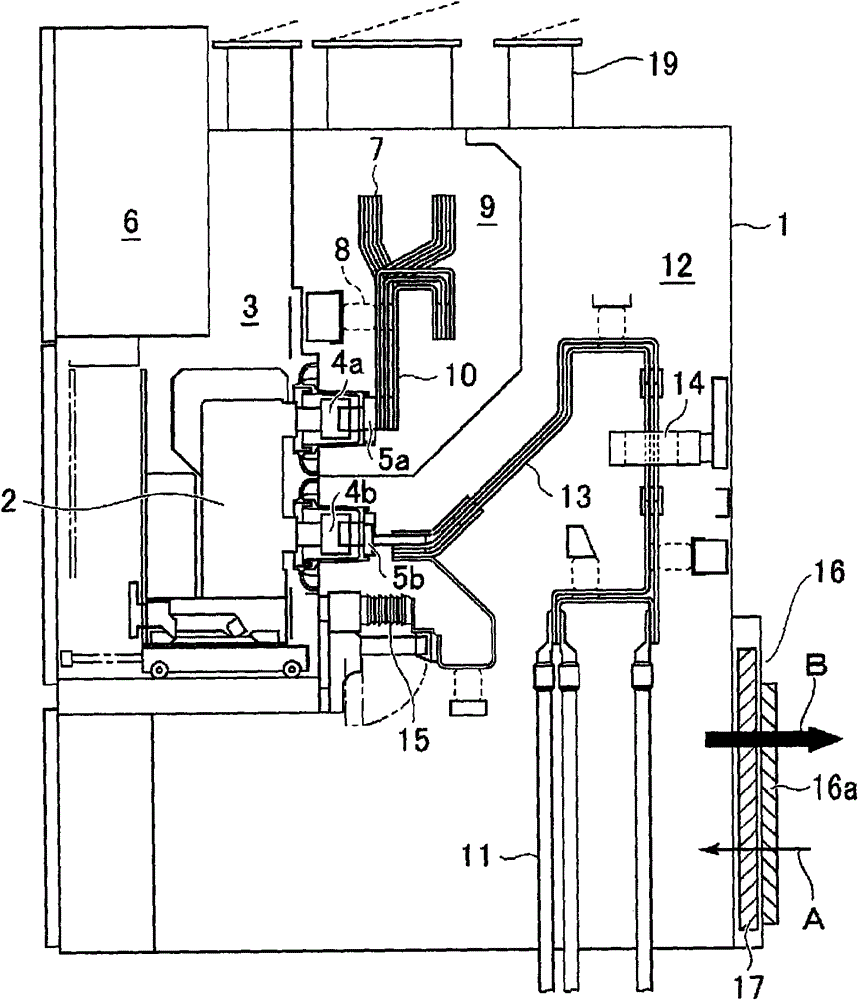
[0026] figure 1 It is a side cross-sectional view briefly showing the switch device according to the first embodiment for implementing the present invention. In the figure, the inside of the grounded metal housing 1 constituting the switch device is divided into a plurality of compartments. On the left (front side) of the figure, a circuit breaker compartment 3 in which a drawable circuit breaker 2 is stored is arranged, and the circuit breaker 2 can be drawn out from the front side. On the rear wall of the circuit breaker compartment 3, disconnecting parts 4a, 4b of the main circuit separated by a predetermined interval up and down are fixedly provided, and can be attached to and detached from a connection terminal protruding to the rear surface of the circuit breaker 2 (right in the figure). In addition, the disconnection parts 4a and 4b are provided with disconnection terminals 5a and 5b. Above the breaker compartment 3 is a control equipment compartment 6 in which control ...
Embodiment approach 2
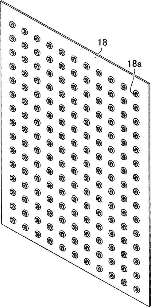
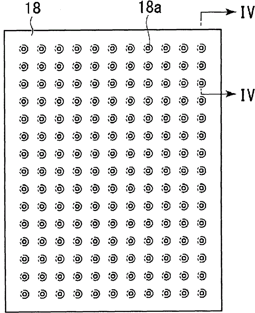
[0042] Figure 8 It is a perspective view showing an irreversible venting member using a plurality of plate-shaped bodies used in the switch device according to the second embodiment of the present invention, Picture 9 Is its main view. In addition, the second embodiment adopts the method in which multiple pieces are arranged in a matrix. figure 2 When the plate-shaped bodies 18 of the through-holes 18a shown are arranged at intervals in the ventilation direction, the center positions of the through-holes formed in the plate-shaped bodies 18 are alternately shifted between adjacent plate-shaped bodies 18 structure.
[0043] In the figure, the plate-shaped body 18A arranged in the central part is provided with a plurality of through-holes 18b in the same matrix as the through-holes 18a. The through-holes 18b are arranged on both sides of the plate-shaped body 18A. The through holes 18a provided on the plate-shaped body 18 have the same shape factor that the fluid energy loss rel...
Embodiment approach 3
[0046] Picture 10 It is a perspective view showing an irreversible vent member used in the switch device according to Embodiment 3 of the present invention, Picture 11 Is a perspective view showing Modification Example 1, Picture 12 It is a perspective view showing Modification Example 2. In addition, in the third embodiment, Figure 7 The multiple plate-shaped bodies 18 shown are provided with fins between each other. in Picture 10 In the non-reversible venting member 17, a plurality of plate-shaped fins 20 extending in the ventilation direction and arranged between two plate-shaped bodies 18 are provided at intervals. The body 18 is the same as in the first embodiment, and is arranged at intervals in the intake direction. In addition, the material of the fin 20 is not particularly limited, but, for example, metals such as iron, aluminum, and copper, or alloys of these metals, or porous sintered metals, or foam alloys can be preferably used. The other structure is the sam...
PUM
 Abstract
Description
Claims
Application Information
 - R&D Engineer
- R&D Manager
- IP Professional
- Industry Leading Data Capabilities
- Powerful AI technology
- Patent DNA Extraction
Browse by: Latest US Patents, China's latest patents, Technical Efficacy Thesaurus, Application Domain, Technology Topic.
© 2024 PatSnap. All rights reserved.Legal|Privacy policy|Modern Slavery Act Transparency Statement|Sitemap