
Pneumatic tire

A technology for pneumatic tires and tires, applied in heavy tires, tire parts, tire treads/tread patterns, etc., can solve problems such as uneven wear, improve uneven wear resistance, inhibit uneven wear, and achieve uniform wear. wear effect

Active Publication Date: 2017-07-28
SUMITOMO RUBBER IND LTD
View PDF9 Cites 4 Cited by
  • Summary
  • Abstract
  • Description
  • Claims
  • Application Information

AI Technical Summary

Problems solved by technology

Therefore, the siping of Patent Document 1 tends to cause uneven wear near the apex of the block wall of the center block

Method used


Image

  • Pneumatic tire
  • Pneumatic tire
  • Pneumatic tire

Examples


Embodiment Construction

[0025] Hereinafter, one embodiment of the present invention will be described with reference to the drawings.

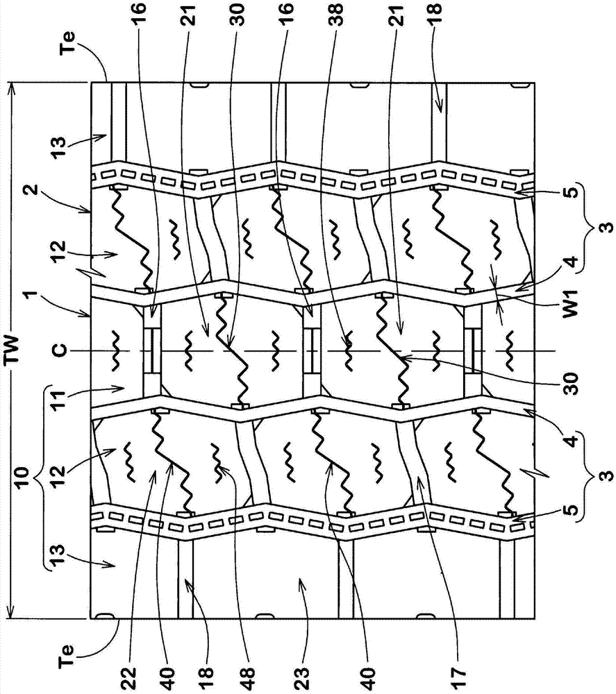
[0026] exist figure 1 A developed view of the tread portion 2 of the pneumatic tire (hereinafter, sometimes simply referred to as "tire") 1 according to the present embodiment is shown in . The pneumatic tire 1 of the present embodiment is preferably used as a tire for heavy loads such as tractors and buses.

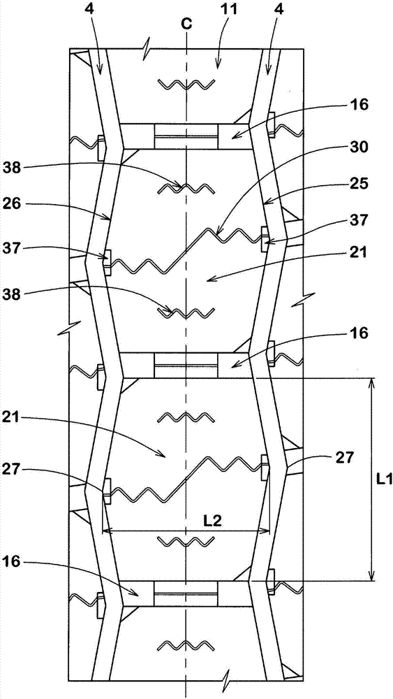
[0027] Such as figure 1 As shown, the tread portion 2 of the tire 1 is provided with a land portion 10 divided by a plurality of main grooves 3 extending continuously in the tire circumferential direction.

[0028] The main groove 3 includes, for example, a pair of center main grooves 4 , 4 and a shoulder main groove 5 . The central main groove 4 is provided as one on both sides of the tire equator line. The shoulder main groove 5 is provided, for example, at a position closest to the tread end Te side.

[0029] "Tread end Te" refers to the ground contact ...


PUM


Abstract

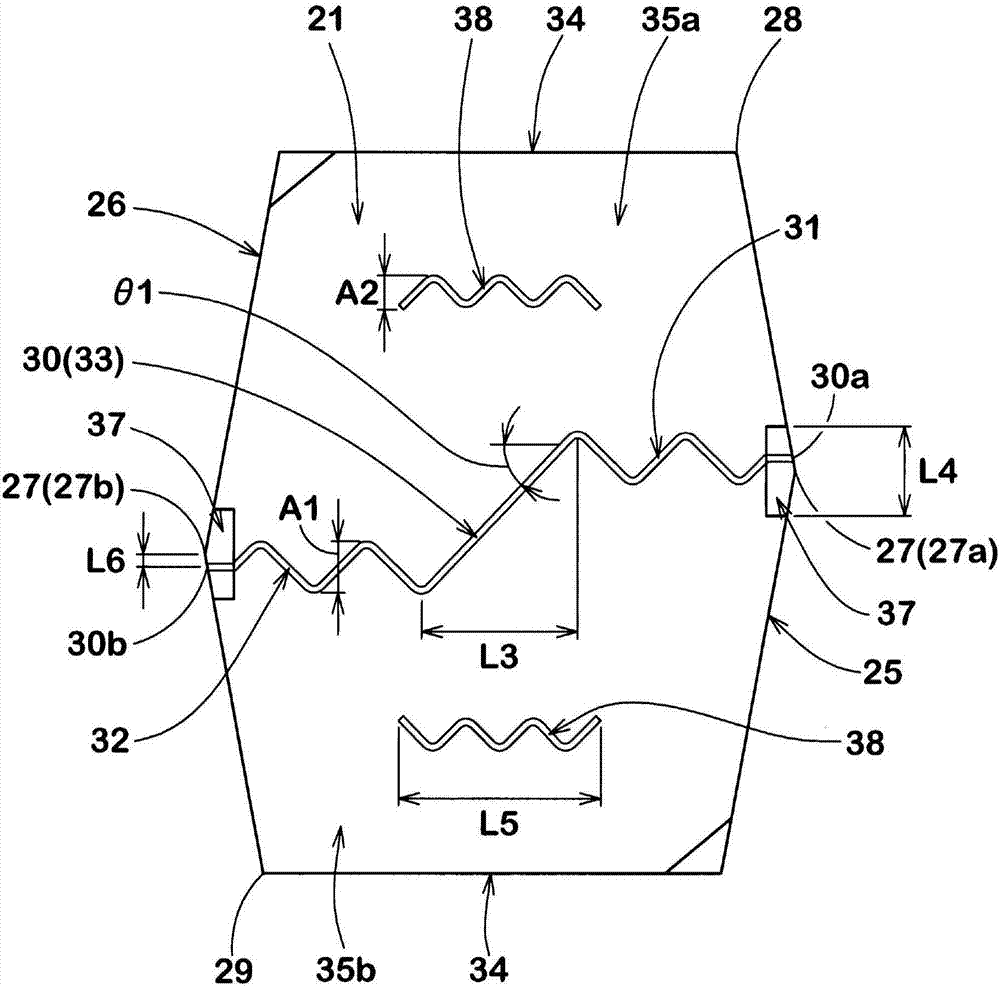
A pneumatic tire is provided and has improved resistance to uneven abrasiveness of center blocks. The pneumatic tire (1) comprises a tread portion (2) provided with crown main grooves (4), a plurality of center axial grooves (16) and a plurality of center blocks (21). The center blocks (21) include a first block side wall (25), a second block side wall (26) and a first sipe (30). The first block side wall (25) and the second block side wall (26) are substantially V-shaped protruding from a vertex (27) respectively. At least a part of the first sipe (30) extends in a waveform manner. One end at the tire axial direction of the first sipe (30) is at one side in the tire circumferential direction of the vertex of the first block side wall (25), and the other end of the first sipe (30) at the tire axial direction is positioned on other side in the tire circumferential direction of the vertex of the second block side wall (26).

Description

technical field [0001] The present invention relates to a pneumatic tire capable of improving uneven wear resistance of a center block provided in a tread portion. Background technique [0002] For example, Patent Document 1 below proposes a pneumatic tire provided with a plurality of center blocks having hexagonal treads. The center block of Patent Document 1 is provided with a sipe that traverses the tread in the tire axial direction. Such sipes can moderate the deformation of the tread when it comes into contact with the ground, and further, it is expected to suppress wear of the heels and toes of the center block. [0003] However, both ends of the sipe in Patent Document 1 are connected to the vertices (vertices of the hexagon) of the block wall protruding outward from the block. Typically, a greater ground pressure acts on the central block and a greater stress acts near the apex of the block wall. Therefore, the sipe of Patent Document 1 tends to cause uneven wear ...

Claims


Application Information

Patent Timeline
Patent Type & Authority Applications(China)
IPC IPC(8): B60C11/03B60C11/12
CPCB60C11/0306B60C11/12B60C2011/0341B60C2011/1209B60C2011/0346B60C2011/1213B60C2011/0358B60C11/11B60C11/1236B60C2200/06B60C11/0304B60C11/1204
Inventor 松田佳惠
Owner SUMITOMO RUBBER IND LTD
Learn More