Vehicle built-in permanent magnet synchronous motor control method

A technology of permanent magnet synchronous motor and control method, which is applied in the direction of motor generator control, electronically commutated motor control, control system, etc., and can solve problems such as system performance deterioration and current amplitude limitation

Active Publication Date: 2020-04-07
武汉多泰科技有限公司
View PDF4 Cites 0 Cited by
  • Summary
  • Abstract
  • Description
  • Claims
  • Application Information

AI Technical Summary

Problems solved by technology

However, this method does not consider the current reverse situation. When the speed or load torque is negatively given, the system will be out of control when the motor current is reversed; and the current amplitude is not limited. When the voltage rise causes the current adjustment System performance will degrade rapidly when the controller goes into saturation

Method used


Image

  • Vehicle built-in permanent magnet synchronous motor control method
  • Vehicle built-in permanent magnet synchronous motor control method
  • Vehicle built-in permanent magnet synchronous motor control method

Examples


Embodiment Construction

[0080] The specific implementation manners of the present invention will be described below in conjunction with the accompanying drawings.

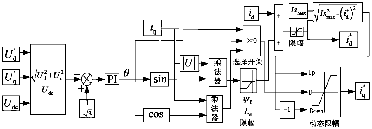
[0081] The vehicle built-in permanent magnet synchronous motor field weakening vector control system of the present invention comprises the following steps:

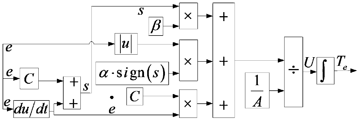
[0082] Step 1. Establish a permanent magnet synchronous motor mathematical model according to specific motor parameters, including a voltage equation model, an electromagnetic torque equation model, and a torque balance equation model.

[0083] Stator voltage equation:

[0084]

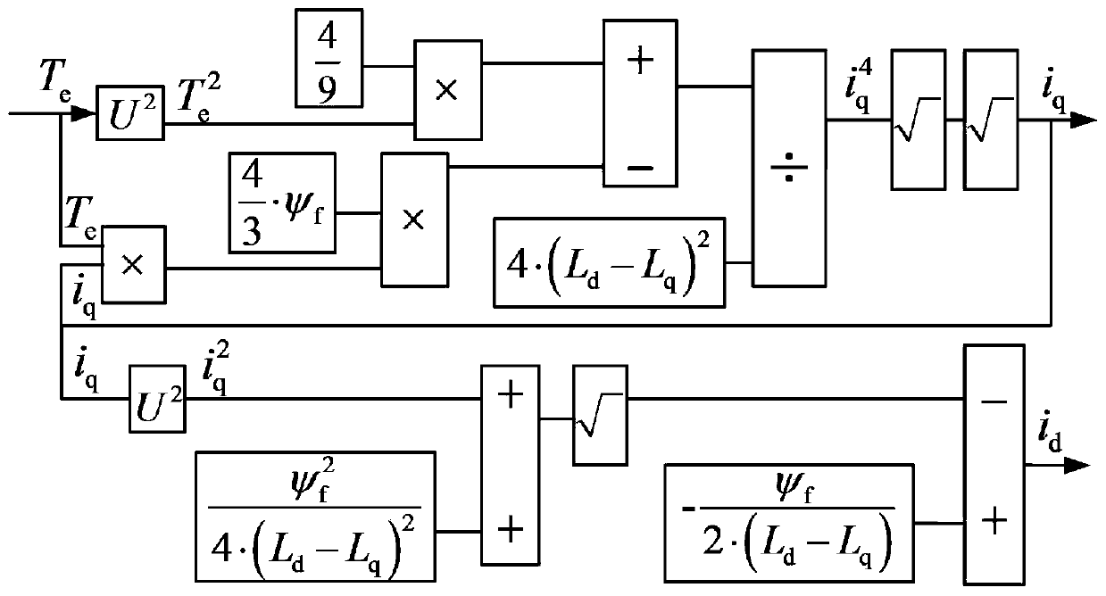
[0085] Electromagnetic torque equation:

[0086]

[0087] In the formula, R s —Stator resistance; p=d / dt—differential operator; i d , i q ; L d , L q —direct axis and quadrature axis current and inductance; ω e =n p · ω r —ω e is the electrical angular velocity, n p is the number of pole pairs of the motor, ω r is the mechanical angular velocity; ψ f - Flux linkage between rotor permanent...


PUM


Abstract

The invention provides a vehicle built-in permanent magnet synchronous motor controlling method. The method comprises steps of 1, establishing permanent magnet synchronous motor mathematic models including a voltage equation model, an electromagnetic torque equation model and a torque balance equation model; 2, designing a sliding mode surface and a sliding mode control law, so as to achieve sliding mode control of the electromagnetic torque of a motor; 3, based on the electromagnetic torque value Te, performing decomposition to obtain a quadrature-axis current iq and a direct-axis current id; 4, based on iq, id, Udc, quadrature-direct axis voltage references U'q and U'd, obtaining quadrature-direct axis current reference values i<*>[q] and i<*>[d] by decomposition; 5, decomposing i<*>[q] and i<*>[d] to obtain the quadrature-direct axis voltage references U'q and U'd; and 6, based on the U'q and U'd, obtaining two phase stationary voltages U[alpha] and U[beta] by coordinate conversion, taking the U[alpha] and U[beta] as the input, and obtaining three phase reference voltages Ua, Ub and Uc after modulating the models to drive an inverter and the motor to work. The control method can ensure stable operation of the motor under any working condition.

Description

technical field [0001] The invention relates to the field of electric vehicle control, in particular to a control method for a vehicle-mounted built-in permanent magnet synchronous motor. Background technique [0002] The built-in permanent magnet synchronous motor has the advantages of wide speed range, high torque current ratio, high power density, high efficiency, high power factor and low noise, and is currently widely used in industrial fields such as electric vehicles. The basic requirements of the vehicle built-in permanent magnet synchronous motor drive system are: at low speed, it is required to output large torque to meet the performance requirements of starting, acceleration and climbing; , Overtaking and other performance requirements. [0003] The common maximum torque-to-current ratio control methods for vehicle built-in permanent magnet synchronous motors in the low-speed constant-torque operation stage include table look-up method and curve fitting method. ...

Claims


Application Information

Patent Timeline
Patent Type & Authority Patents(China)
IPC IPC(8): H02P21/22
Inventor 刘斌赵越蒋峥胡慧中
Owner 武汉多泰科技有限公司
Why Eureka
Try Eureka