

Method and device for generating halo effect diagram
A technology for renderings and images, applied in the field of image processing, can solve problems such as the inability to accurately determine the light source of the image
- Summary
- Abstract
- Description
- Claims
- Application Information
AI Technical Summary
Problems solved by technology
Method used
Image

Examples
Embodiment 1
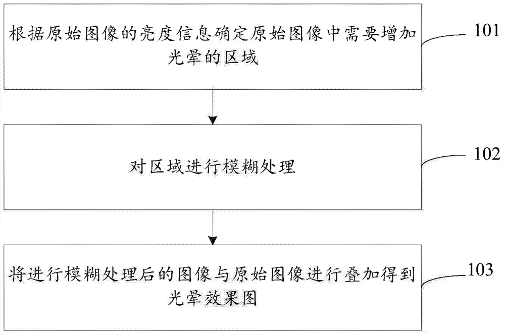
[0020] This embodiment provides a method for generating a halo effect map, figure 1 is the flowchart of the method, such as figure 1 As shown, the method includes the following steps:
[0021] Step 101: Determine the area in the original image where halo needs to be added according to the brightness information of the original image;
[0022] Preferably, according to the brightness information of the original image, determining the area where the halo needs to be added in the original image includes: converting the color value of the original image to obtain a brightness value; that is, converting the image from an RGB value to an HSV value, where V is the brightness value, and determine the area formed by the pixels whose luminance value is higher than the preset threshold as the area in the original image where halo needs to be added, hereinafter referred to as the light source area.
[0023] Step 102: blurring the region;
[0024] In this step, blurring the light source ...
Embodiment 2
[0028] This embodiment further illustrates the method for generating a halo effect map provided by the present invention by disclosing more technical details.
[0029] First, you need to specify the light source in the object. The color and brightness of the light source will be directly converted into the color and brightness of the final halo that needs to be realized. Therefore, you can control the appearance of the halo by changing the brightness of the light source. In this embodiment, the light source can be a geometry specified by some object's attributes or flags, or limited to a small part of the object using texture data. For the latter case, the texture data can be made to mask the non-illuminant sources, rendered as black, and the illuminant part can be set to the desired color and brightness. The preferred way to accomplish the above steps is to use texture data, which is convenient and makes the rendered object more artistic.
[0030] Different from the traditio...
Embodiment 3
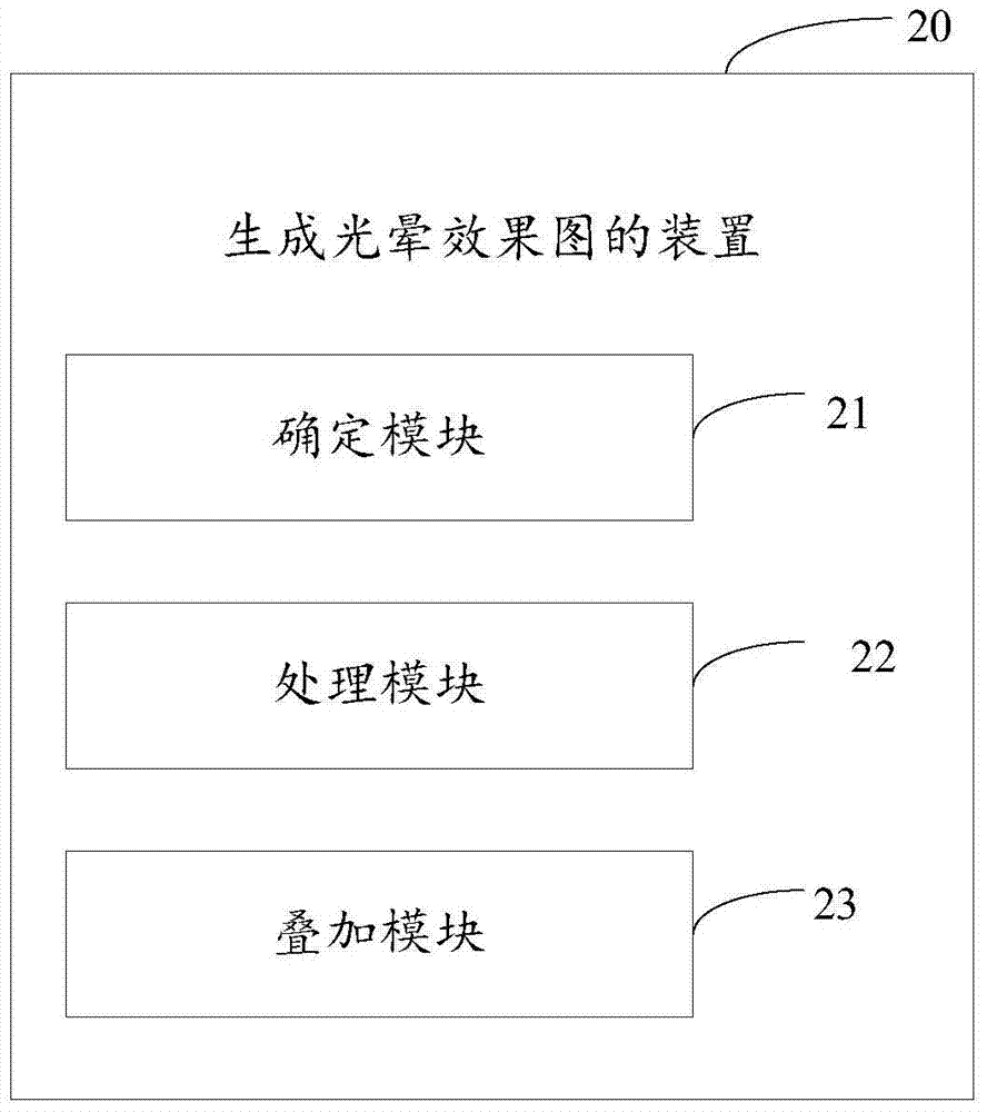
[0034] This embodiment provides a device for generating a halo effect diagram, which is used to implement the methods for generating a halo effect provided in Embodiment 1 and Embodiment 2 above, figure 2 is the block diagram of the device, such as figure 2 As shown, the device 20 includes the following components:
[0035] Determining module 21, is used for determining the region that needs to increase halo in the original image according to the brightness information of the original image;
[0036] A processing module 22, configured to perform blurring processing on the region;
[0037] The overlay module 23 is configured to overlay the blurred image and the original image to obtain a halo effect image.
[0038] Wherein, the above-mentioned determination module 21 may specifically include: a conversion unit for converting the color value of the original image to obtain the brightness value of the image; a determination unit for determining an area composed of pixels whos...
PUM
 Abstract
Description
Claims
Application Information